16
Proportional Pressure Valves
Series RE*T / R*V
Operation Manual
Parker Hannifin Corporation
RE_-R_V obe_24-45-A-B 5715-651 UK 29.01.19
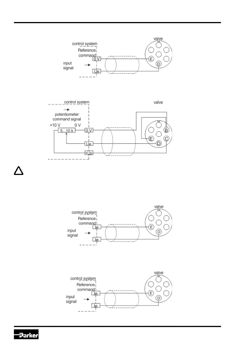
Wiring diagram of voltage command input 0...+10 V code F/10V
Wiring diagram of voltage command input 0...+10 V via potentiometer code F/10V
The external potentiometer is fed via the output “potentiometer supply”. To prevent this output from
overload, the resistance value of the potentiometer should be within a range of 5...10 kOhm. A
nominal power rating of 0.1 W is sufficient.
Wiring diagram of current command input 0...20 mA code G
Wiring diagram of current command input 4...20 mA code R/4MA

 Loading...


