24
GB/CY
U
To forestall or reduce deformations that
can happen during the material harden-
ing process, it is good to fi x the work-
piece with a device. Avoid stiffening the
welded structure to prevent cracks in the
weld. These problems can be avoided if
there is a possibility of turning the work-
piece so that the weld can be carried
out in two passes running in opposite
directions.
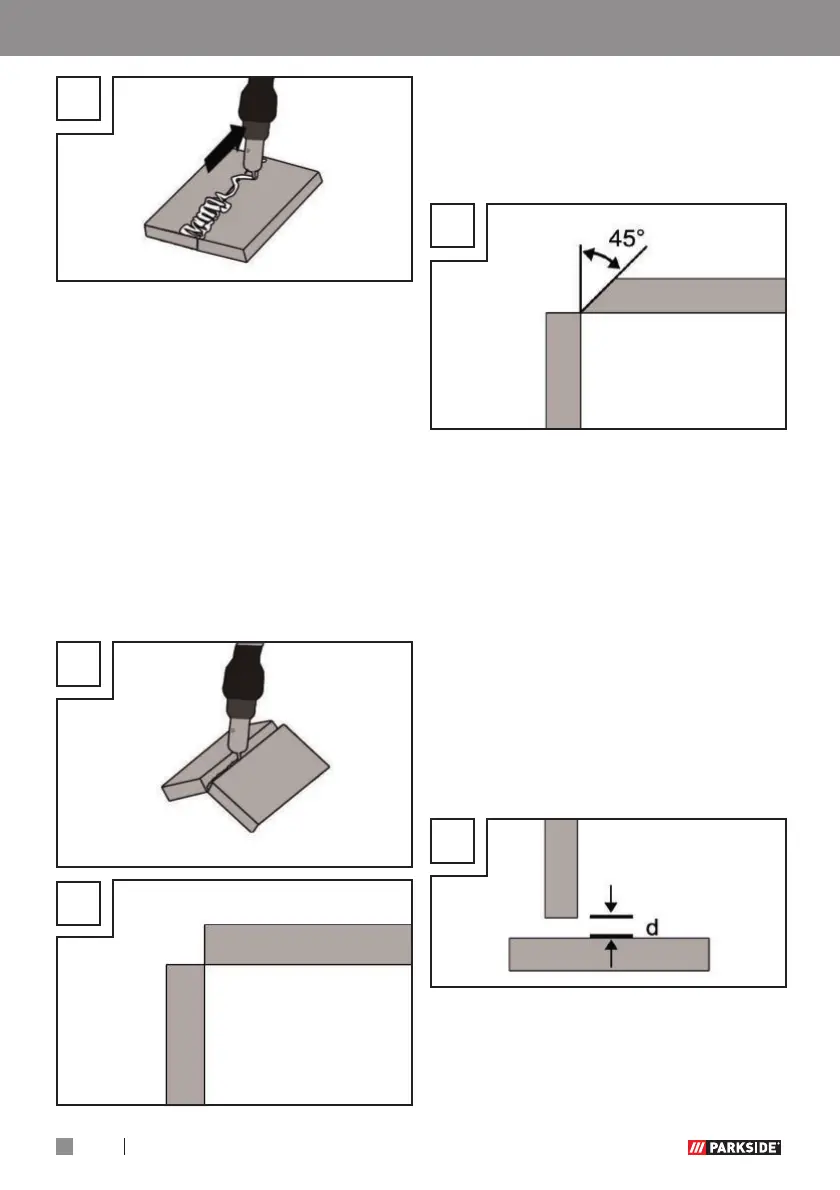
Welds on the outer edge
The preparation for this is very simple
(Fig. V, W).
V
W
However, it is no longer expedient for
thicker materials. In this case, it is better
to prepare a joint as shown below, in
which the edge of the plate is angled
(Fig. X).
X
Fillet weld connections
A fi llet weld is created if the workpieces
are perpendicular to each other. The
weld should be shaped like a triangle
with sides of equal length and a slight
fi llet (Fig. Y, Z).
Welds on an inner edge
The preparation for this weld joint is very
simple and is carried out for thicknesses
of 5 mm. The dimension “d” needs to
be reduced to a minimum and should
always be less than 2 mm (Fig. Y).
Y
However, it is no longer expedient for
thicker materials. In this case, it is better
to prepare a joint as shown in Figure X,
in which the edge of the plate is angled.
Using the device