PBI-Dansensor A/S COPYRIGHT © PBI-220047-F 01/2008
41
MAP Check 9000 - User Manual 10. Specifications
10.5. Control and connection
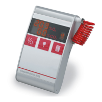
MAP Check 9000 control:
•Display: 4-digit red LED display (not MAP Check 900X-2)
•Control: 4 front keys. No key function is activated until the key in
question is released. (Not MAP Check 900X-2).
•Measuring accuracy: More accurate than +/- 1% of the value measured +/- 1
digit in calibrated measuring range
•Measuring ranges: 20.9 % - 1 ppm for MAP Check 900X-1/-2
20.9 % - 0.01 pppm for MAP Check 9001-4
Possible connections to the MAP Check 9000:
•Gas supply: Gas inlet on the back
•CAN bus: Data transmission to and from a soldering machine or the
like (option).
•RS232C: Serial communication. For connection of e.g. PC.
Used for data transmission to PC and/or remote control of
MAP Check from e.g. PC (option).
•Alarm relays: 2 user-defined relays (O
2
- alarms). Max. 48V,1A
1 flow / system error / ready relay. Max. 48V,1A
•Current outputs: Up to two outputs, programmable 0-20 or 4-20 mA, with
user-defined scale (e.g. 0-1 %, 10-20.9 % or 0-100 ppm
O
2
) (option).
•Voltage outputs: Up to two outputs, programmable 0-10V or 2-10V, with
user-defined scale (e.g. 0-1 %, 10-20.9 % or 0-100 ppm
O
2
) (option).
•Measure input: 10-32VDC external pump control. Consumption: 10mA.
All electrical inputs and outputs have been galvanically separated from the internal
electronics by means of optocouplers.