Install the device(s) and supply power from the system power unit.
Use the cable provided to connect the device(s) to the Primary IDE
channel connector IDE1 on the mainboard.
If you want to install more IDE devices, you can purchase a second
IDE cable and connect one or two devices to the Secondary IDE
channel connector IDE2 on the mainboard. If you have two devices
on the cable, one must be Master and one must be Slave.
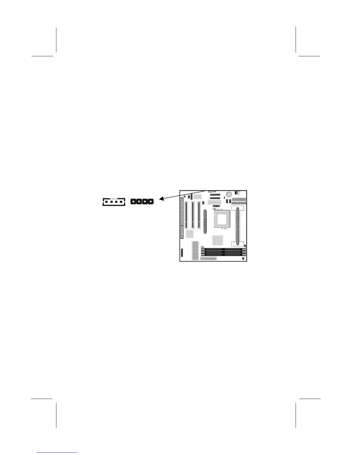
Internal Sound Connections
If you have installed a CD-ROM drive or a DVD drive, you can
connect the sound output of the drive to the built-in sound system.
You can connect the analog audio output to the analog connectors
CD1 or CD2.
On the mainboard, locate the two 4-pin connectors for CD1 and
CD2. The illustration shows the ground pins (G) and the pins for
the left (L) and right (R) audio channels. There are two kinds of
connector because different brands of CD-ROM/DVD drives have
different kinds of cable connectors on their audio output cable.
Connect the cable to the appropriate connector.
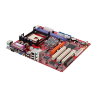
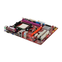
Expansion Slots
This mainboard has one AGP slot, three 32-bit PCI expansion
slots, and one 8/16-bit ISA slot. The first PCI slot (PCI1) is shared
with the ISA slot (ISA1). This means that you can use either one of
these slots but you cannot use both slots at the same time.
CD2
CD1
G L G R L G G R