PCTEL, Inc. Page 15 of 42 Rev T
3. Installation
This section describes how to set up the
SeeGull IBflex scanning receiver.
3.1. Integration
There are eight (8) mounting holes (4-40
screw) on the chassis of the unit that are
used for mounting in the user’s
enclosure/rack. Note that the maximum
depth of screw insertion from the chassis
exterior is ¼”. Refer to Figure 2 and Figure
4. Care should be taken when mounting this
unit in a system enclosure, rack, or case.
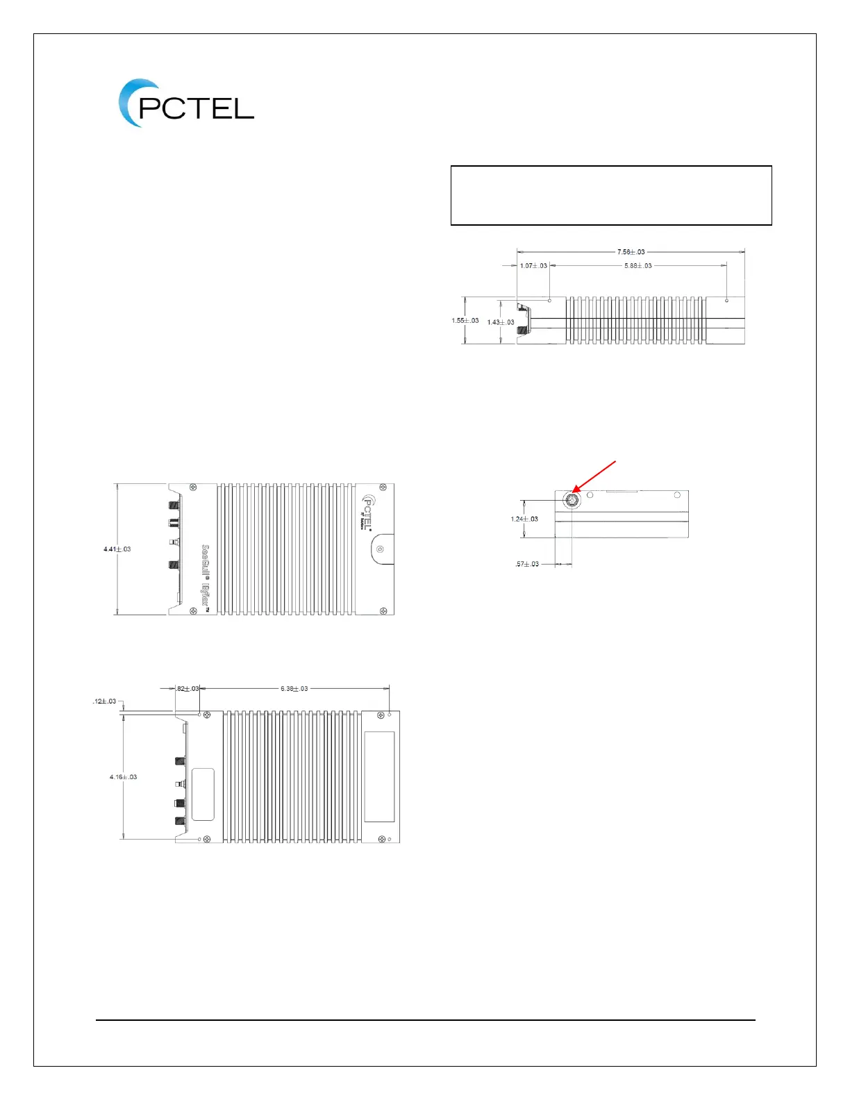
Figure 2 - SeeGull IBflex Scanning Receiver
Top View (without battery pack)
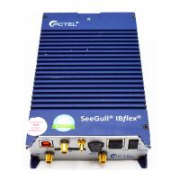
Figure 3 - SeeGull IBflex Scanning Receiver
bottom view (without battery pack)
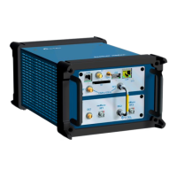
Figure 4 - SeeGull IBflex Scanning Receiver
Side View (without battery pack)
Figure 5 - SeeGull IBflex Scanning Receiver
Rear View (without battery pack)