PCTEL, Inc. Page 39 of 42 Rev T
11. Appendix C: NB-IoT Measurements
11.1. NB-IoT: Introduction
PCTEL is introducing a new measurement to quantify the KPI metrics of the NB-IoT
network. This application note will discuss the new features of this measurement.
11.2. NB-IoT Physical Layer
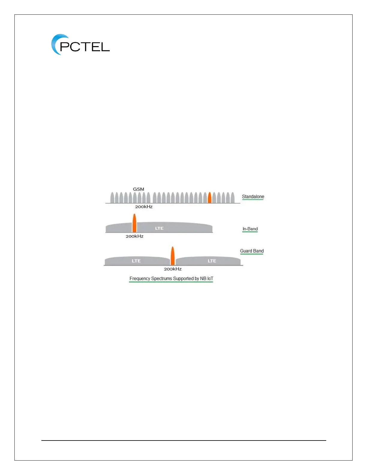
The NB-IoT physical channels can be located as a stand-alone network or they could be
part of a standard LTE network in Guard-band and In-Band spectrum. Below is a representation
of these signals.
Figure 28 - NB-IoT
11.3. Top N NB-IoT Signal Measurement
Below is a list of key features of the new measurement.
• The NB-IoT carrier follows the 3GPP FD-LTE channel raster. It has a channel index
value of 100 kHz. To align the NB-IoT signal with standard LTE the 3GPP standard
introduces a frequency offset value from the channel raster. The values of the offset
could be 0, +/-2.5 kHz and +/- 7.5 kHz. The scanner will calculate this value as
explained below.
• The user must select the ‘operation mode’ to determine whether the network is stand-
alone, Guard-band or In-Band.
• When the user selects the ‘stand-alone’ they must provide the channel or frequency of
the NB-IoT network. In this mode the scanner calculates the frequency offset as zero.