Three phase motor
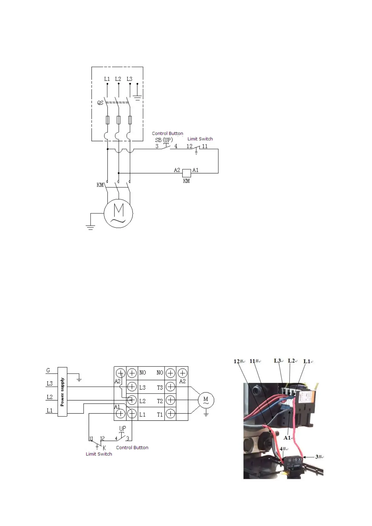
1. Circuit diagram (See Fig. 41)
2. Connection step (See Fig.42)
a. The source wires (L1, L2, L3) are connected with terminals of AC contactor
marked L1, L2, L3 respectively.
b. Terminals 4# of control button is connected with wire 12#(brown wire) of limit
switch; wire 11#(blue wire) is connected with A1 terminal of AC contactor, Earth
wire( yellow and green wire) of limit switch is connected with the earth wire
terminal of the motor.
C. Terminals 3# of control button is connected with L1 terminals of AC contactor.