21
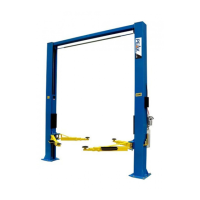
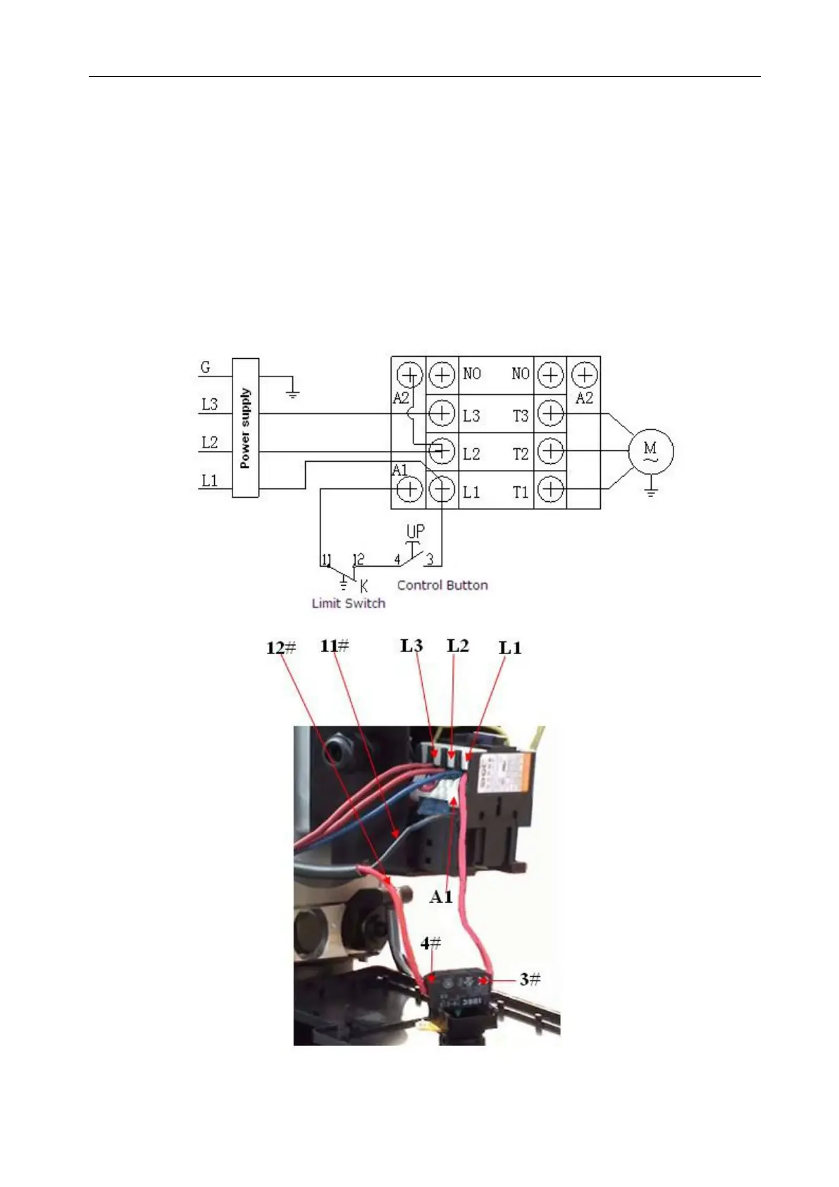
2. Connection step (See Fig. 36)
a. The source wires (L1, L2, L3) connected with terminals of AC contactor marked
L1, L2, L3 respectively.
b. Terminals 4# of control button connected with wire 12# (brown wire) of limit
switch; wire 11# (blue wire) connected with A1 terminals of AC contactor, Earth
wire ( yellow and green wire) of limit switch is connected with terminal earth wire
of the motor.
C. Terminals 3# of control button connected with L1 terminals of AC contactor.