EasyManua.ls Logo

Peak 409A - 380 V Wire Connection and Circuit Diagram; Wire Connection Diagram in the Control Box; 380 V Wire Connection Diagram of Hydraulic Motor

Peak 409A
52 pages
Print Icon
To Next Page IconTo Next Page
To Previous Page IconTo Previous Page
Loading...
23
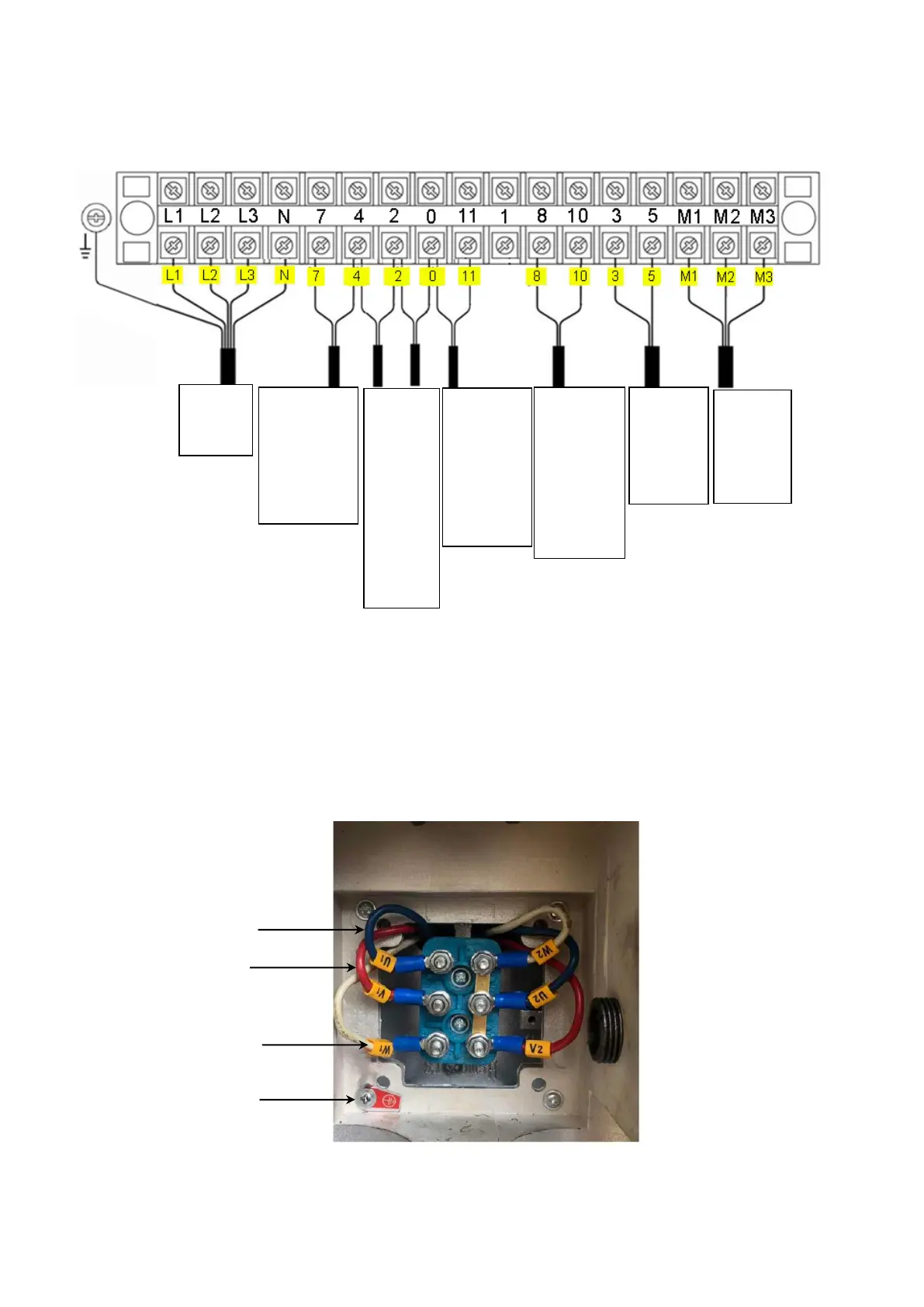
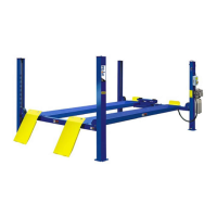
5. 380V Wire connection and circuit diagram
5.1 Wire connection diagram in the control box (See Fig.49).
5.2 380V Wire connection diagram of hydraulic motor (See Fig.50).
Motor wire (M1M2M3) are connected to the three wires in the motor.
Turn on the power, push button “UP, if motor run but lift is not worked, please
exchange the M1, M2 wires connection.
Fig. 49
Fig. 50
M2(Red)
Earth Wire
(Green & Yellow)
M1(Blue)
M3 (White)
Wire
of
motor
High
limit
switch
wire
C
Power
wire
Wire
A
B
of
limit
switc
h on
cross
beam
Wire of
hydraulic
solenoid
valve
Air
solenoid
valve
wire
Lower
limit
switch
wire
D

Table of Contents

Related product manuals