11
2005 Doctor Martin Luther King Jr Street
Indianapolis, IN 46202
Rev 07-2021
Preparation of tube sections:
Prior to assembling the tube
sections, inspect the tube faces to ensure
that they are free of nicks or burrs. Any
flaws on the tube end faces must be
removed prior to assembly, to ensure
proper mating of tube surfaces.
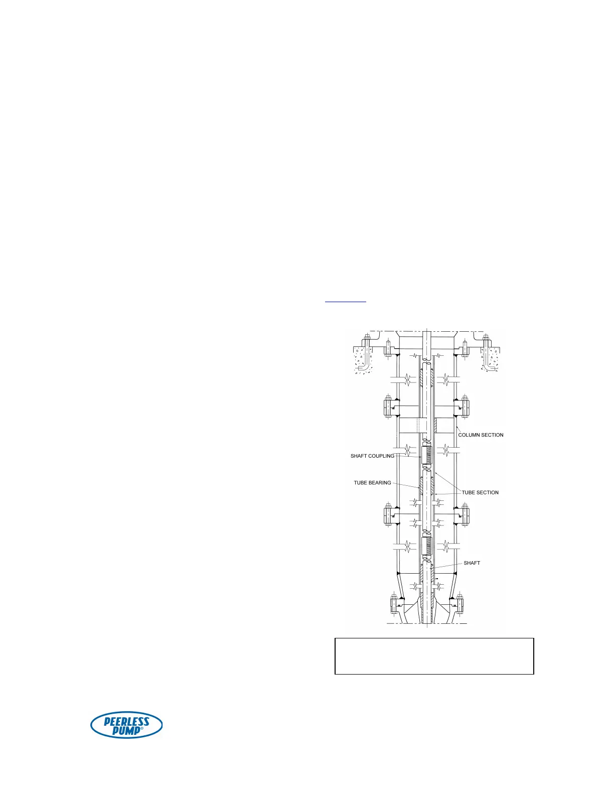
The tube sections are coupled by
tube bearings. Lubricate tube bearing
threads. Assemble the tube bearing onto
one tube, threading it in one-half of its
total length. Tube sections are furnished
in two different lengths: ten feet and
twenty feet. The ten-foot sections are
actually two five-foot sections, internally
threaded and coupled by an externally
threaded tube bearing; likewise, the
twenty-foot sections consist of four
coupled five-foot sections (see Fig. 3).
The top tube section is different and
may be identified by the external thread
at the upper end. It may be one piece or
coupled by means of a threaded tube
bearing to a “second top tube”
combining for a length that may be
different than the standard section
lengths. The tube section just below the
top tube is shorter than standard—
usually 3′4″. The top column section is
never fitted with a coupling, since the
upper end screws directly into the
discharge head or into a special flange.
While the bowl assembly is still in a
horizontal position, push the shaft down
as far as it will go and measure the
distance from the top bowl flange to the
top of the shaft. The normal
measurement is 20″. The distance from
that same flange to the top of the tube
adaptor face should be 10″. This
dimension is frequently referred to as
“10/20 stickup”.
If the dimensions on the bowl assembly
are different than those stated above, do
not proceed with installation; contact a
Peerless Pump representative as there
may be special instructions for your
bowl assembly.
Having recorded the first
measurement, now pull the shaft toward
you (or up) as far as you can and take a
second measurement. The difference
between the first and second
measurements is the total axial
movement of the impeller. This
clearance is normally ½″ ± ⅛″ (see
Table 4 on pages 37-39 for specific
dimensions).
Figure 3. Sectional view through
enclosed lineshaft column.