23
2005 Doctor Martin Luther King Jr Street
Indianapolis, IN 46202
Rev 07-2021
After the discharge head is installed
on the pump column, always use the
lifting ears on the discharge head for
hoisting the pump. If the discharge head
does not have lifting ears, pass the slings
through the hand holes, taking care that
the slings do not interfere with the shaft.
Never attempt to lift the pump by
means of eyebolts screwed into the
driver mounting holes because the
bolts are not strong enough to carry
the weight of the entire pump.
LEVELING THE PUMP
Remove the supporting timbers,
rope and any other equipment from the
top of the foundation. Cover the
discharge head to protect it from dust,
and sweep the foundation clean.
If the sole plate is not already
grouted in place, be certain that the
grouting dam around the foundation
opening is in place before lowering the
pump assembly onto the foundation.
Lower the pump until the base of
the discharge head or sole plate is just
above the foundation bolts; then orient
the pump so that the discharge outlet is
in the desired direction and the holes in
the base align with the foundation bolts.
Continue to lower the pump until the
bolts just enter the holes in the base.
If the foundation is concrete, place
the wedges (furnished with the pump)
under the discharge head or sole plate,
adjacent to the bolt holes, one under
each of the four sides. For structural
foundations (made up of I-beams or H-
beams), use flat shims under the corners.
Continue to slowly lower the pump
until the base of the discharge head or
sole plate rests on the shims or anchor
bolts with washers and nuts.
Accurate alignment of the discharge
head in relation to the pump shaft is
absolutely essential for a smoothly-
operating and trouble free pumping
system.
By using the wedges or washers and
nuts on the anchor bolts, adjust the
discharge head flange centerline to the
correct elevation.
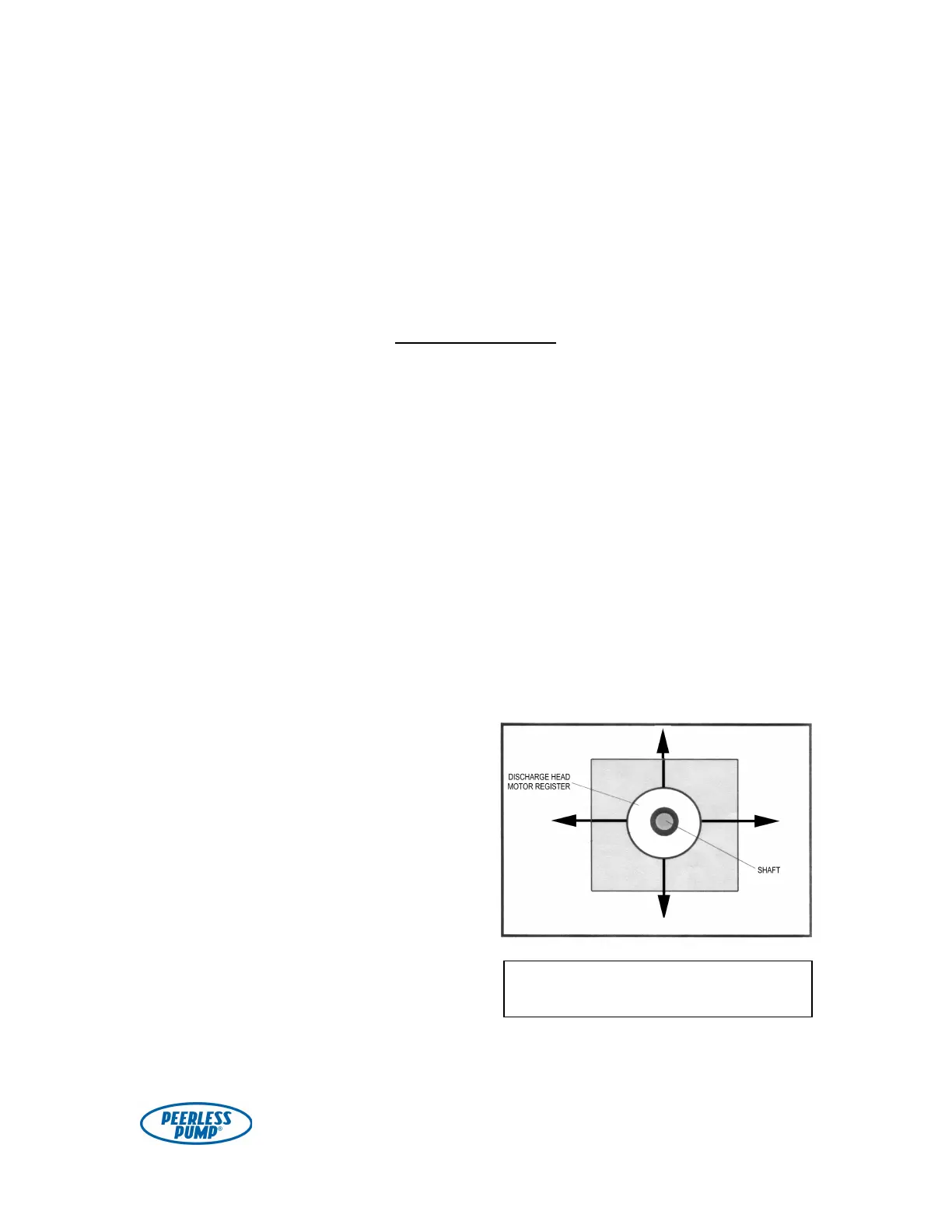
While maintaining the correct
elevation, adjust the nuts and washers or
shims to achieve the specified levelness
(0.0005" per foot) in both directions, as
shown in Figure 16. The levelness
should be measured by placing a
precision level on the machined face of
the discharge head motor register.
Figure 16. Check for levelness in two
directions.