36
2005 Doctor Martin Luther King Jr Street
Indianapolis, IN 46202
Rev 07-2021
IMPELLER CLEARANCE ADJUSTMENT
Lock out the electrical power
source before working on the pump.
With the top drive coupling securely
fastened to the motor rotor, check the gib
key fit to the top shaft keyway. The key
fit should be such that one can slide the
key inside the shaft keyway by hand.
Rotate the top drive coupling until
its keyway is aligned with the top shaft
keyway. The key must fit snugly against
the sides of the keyways, but must have
a slight clearance with the bottom of
each keyway. File the key, if necessary,
with a smooth mill file to obtain the
proper fit. Coat the gib key with anti-
seize compound and install in keyway
(see Fig. 21).
Prior to installing the brass adjusting
nut, take a marking pen and scribe radial
marks from of all the drilled and tapped
holes to the outside circumference.
These marks will allow you to more
easily locate the holes after the top
adjusting nut is installed.
At this time, attempt to manually
rotate the pump and motor counter-
clockwise. No rotation should be
possible if all the threaded line shaft is
mated and the impeller is resting on the
suction manifold. If any free rotation of
the pump and motor can be made, it is an
indication that the line shaft has come
unscrewed. If possible, try to determine
the location of the loose line shaft. If this
is not possible, continue to rotate the
pump and motor counter-clockwise until
it stops.
On small pumps at short settings
where the rotating element of the pump
is relatively light, rotation of the shaft
may be felt but some resistance would
be encountered (shaft would not freely
spin).
Install the brass adjusting nut on the
top shaft and screw down until it makes
light contact with the face of the top
drive coupling. Do not tighten yet.
Measure the distance from the face
of the motor top drive coupling to the
top of the top shaft. Record this
measurement.
Turn the adjusting nut in a right-
hand rotation until the dimension that
was recorded is increased by 3/16", or
by the recommended impeller clearance
as shown in Table 4 on pps. 37-39 (see
Fig. 21). After the pump has operated for
a minimum of one hour, or when the
water is clear of foreign material, the
impeller clearance can be reset if so
desired, but this is not required for
normal pump operation.
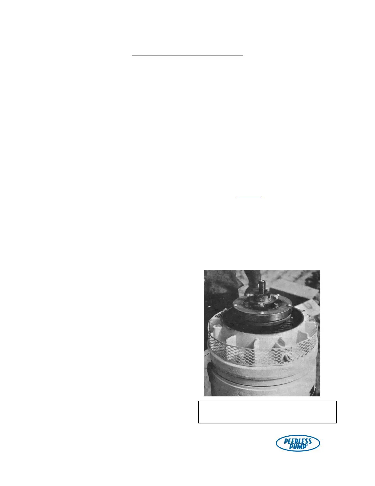
Figure 21. Gib key inserted into top shaft and
top drive coupling.