15
2005 Doctor Martin Luther King Jr Street
Indianapolis, IN 46202
Rev 07-2021
INSTALLATION OF SHAFT, ENCLOSING TUBE, AND COLUMN
Preferred method:
Head room permitting, lift the
appropriate-length shaft into a vertical
and plumb position. Check shaft threads
for any foreign materials or damage, and
clean threads with a wire brush and
solvent as required.
Shaft threads are left-hand, and
must be clean and de-burred!
Coat the shaft face and threads with
anti-seize compound. Check the shaft
coupling for any damage or foreign
material, and clean if necessary.
Screw coupling onto shaft for half
its distance. Approximately 1½ shaft
threads will be visible when coupling is
in half-way position. Another check for
correct positioning of the coupling on
the shaft is to insert a fine wire into the
drilled hole in the center of the coupling.
Visually inspect the shaft threads
and face of the mating shaft. Coat them
with anti-seize compound.
Lower the shaft and coupling onto
the lower (bowl unit) shaft. Manually
screw coupling until tight. If resistance
is encountered, remove the coupling and
shaft, and inspect the threads at both the
coupling and shaft to determine the
problem. Because the threads of the
shaft and coupling are straight (not
tapered), you should be able to tighten
them by hand until the two faces mate.
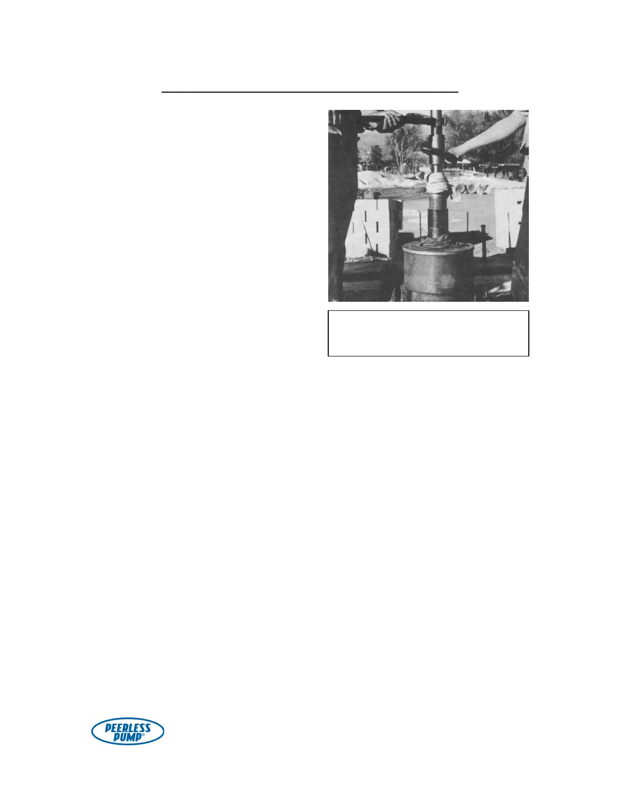
Check the tightness of the mating by
using two pipe wrenches as shown in
Fig. 8.
No noticeable movement should
occur when the pipe wrenches are used
to check the tightness of the hand-
mating. If movement is noticed, it would
be an indication that foreign material has
gotten between the faces of the two
shafts and, by using the wrenches, you
are causing movement by compressing
the foreign material. This is not
acceptable: the shafts should be
disassembled, the foreign material
removed, and any scoring on the shaft
faces should be corrected.
Check to make sure that the threads
on the first enclosing tube section are
clean and free of damage. Lift the five-
foot tube section over the shaft and
lower it onto the upper tube adaptor
bearing.
Using two large pipe wrenches or
chain wrenches, tighten the five-foot
tube section against the tube adaptor (see
Fig. 9). Note that subsequent
tube/bearing assemblies will be
completed horizontally (before hoisting
the sections).
Figure 8. Making a shaft joint. Note the
clean rag and wooden apron protecting
bowl unit and tube bearing.