16
2005 Doctor Martin Luther King Jr Street
Indianapolis, IN 46202
Rev 07-2021
Fill the first five-foot section with
the same heavy-weight oil that was
installed on the tube adaptor. This oil,
being more viscous than the turbine oil
that will used from this point forward,
will act as a barrier to prevent the
lighter-weight turbine oil from leaking
out through the bypass ports. At the
same time, as the pump is lowered into
the sump, this will help prevent the
water in the sump from entering the
enclosing tube through the open bypass
ports.
Install the tube bearing into the
section five-foot tube section, screwing
coupling halfway in. Lower the
tube/bearing assembly over the shaft
onto the tube bearing of the first five-
foot section and tighten.
Connect a dragline to the lower end
of the column flange, to be used in
guiding and aligning the column over the
shaft (see Fig. 10).
The use of the dragline will prevent
accidental bumping of the shaft by the
column that could bend the shaft.
If
gaskets or
O-rings are
used
between
the flange
joints,
install the
appropriate gasket/O-ring on the bowl
flange.
Lift the first column section (usually
tapered) over the shaft, and then lower it
onto the top bowl/discharge manifold
flange. After ensuring that the two
flanges are properly registered, install
fasteners and tighten in an alternating
pattern.
At this time perform another
measurement check from the column
flange to the top of the enclosing tube
and to the face of the lineshaft; these
dimensions should be 10 and 20 inches,
respectively. If your measurements
differ from the standard 10/20 stickup,
do not proceed until you are able to
determine why you do not have a 10/20
stickup. Consult Table 4 on pps. 37-39
for precise dimensions for your pump.
Prior to installing the second
lineshaft, pour turbine oil down the
enclosing tube before installing the tube
bearing. After the enclosing tube is filled
with oil, screw the tube bearing into the
enclosing tube.
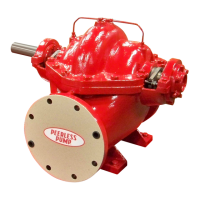
Figure 10. Hoisting column section.
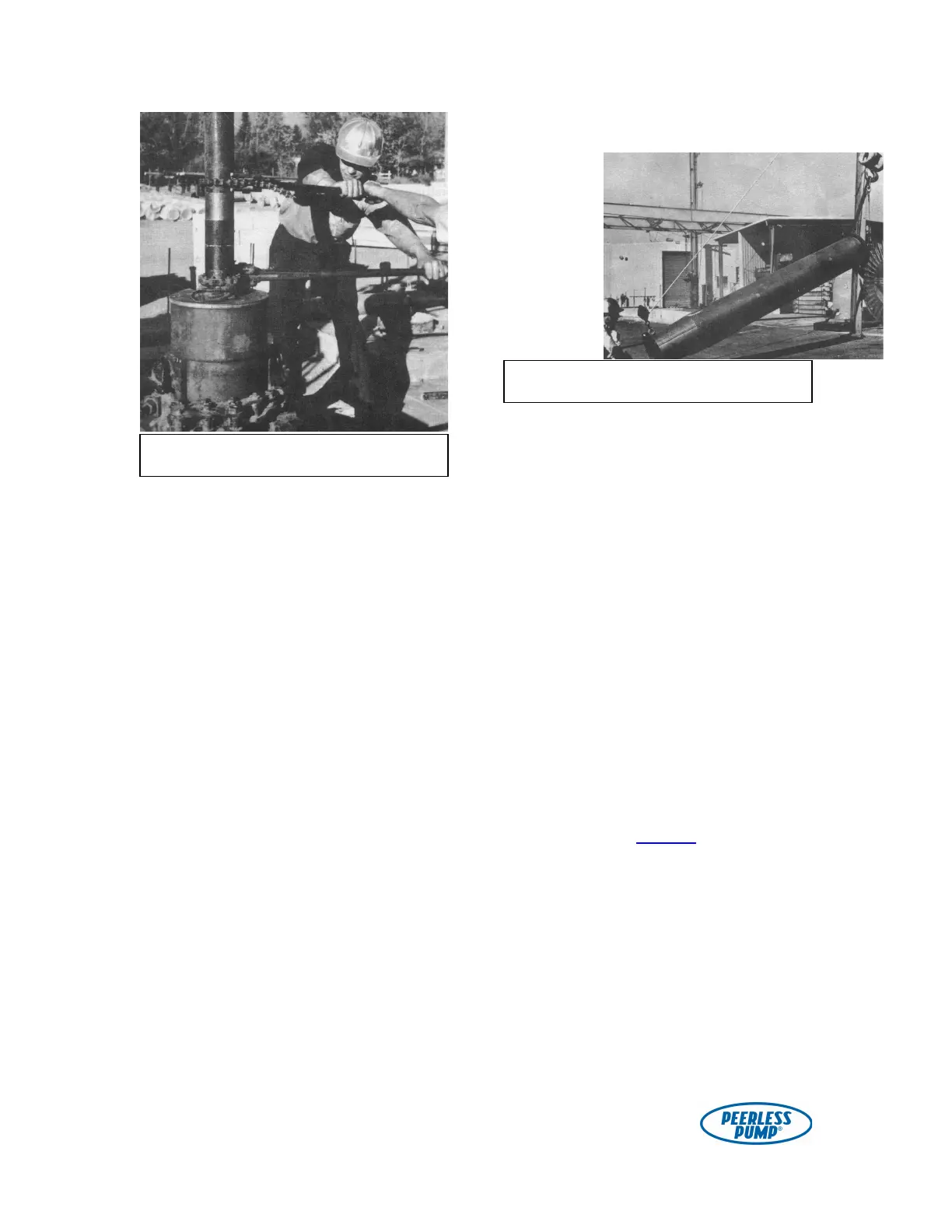
Figure 9. Making a tube joint.