5
2005 Doctor Martin Luther King Jr Street
Indianapolis, IN 46202
Rev 07-2021
BUILDING THE FOUNDATION
It is strongly recommended that a
substantial concrete foundation be built
around the well or sump before the
pump is installed. The original pump
shaft alignment will last only as long as
the foundation supports the pump in a
stable position.
For well installation only:
If the pump discharge head has a
protrusion below the base that is wider
than the well casing, the top of the
casing must be far enough below the
foundation surface to clear such a
protrusion. In this case, a dam must be
provided around the well casing to retain
the grout that will later be poured
between the discharge head and the
foundation. If the well casing is wider
than any protrusion of the discharge
head below the base, the casing itself can
be used as a dam for the grout.
The thickness of the foundation must
be adequate for inherent stiffness, and
the ground area sufficient to provide a
stable footing. Minimum thickness and
ground area are determined by two
factors:
1. The firmness of the supporting
earth, considering adverse effects
of rain and flooding.
2. The total weight of the complete
pumping unit when full of water.
Total load on foundation =
Weight of all parts + Weight of
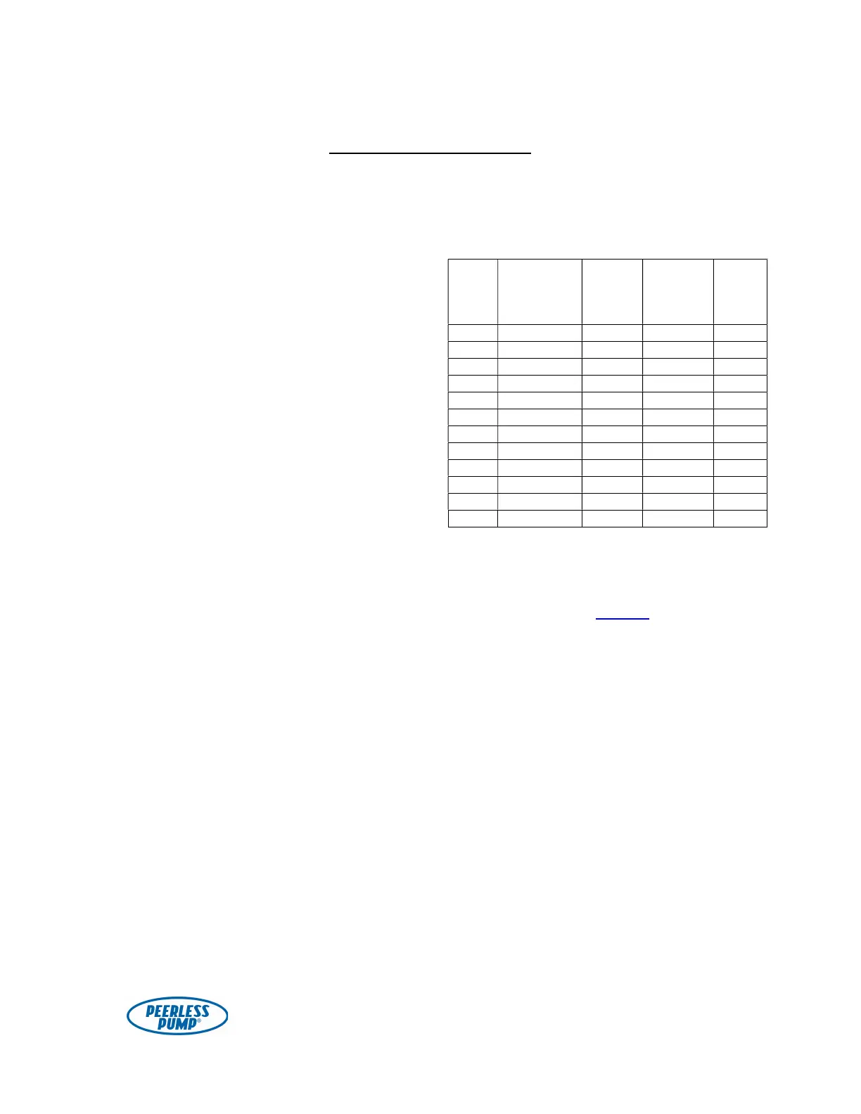
water in column. Table 1,
below, may be used for reference
in figuring the size of the
foundation. See the construction
drawing for weights of all pump
components.
Table 1. Approximate Weight of
Water-Filled Pump Column (lbs.)
Nom.
Pipe
Size
Schedule
(Wall
Thickness)
Wt. per
Ft. of
Pipe
Wt. of
Water
per Ft.
of Pipe
Total
Wt.
per
Ft.*
3 40 7.58 3.0 10.6
4 40 10.79 5.0 15.8
5 40 14.62 8.0 22.6
6 40 18.97 12.0 31.0
8 30 24.70 20.0 44.7
10 (.279) 34.24 23.0 57.2
12 30 43.77 48.0 91.8
14 30 54.57 57.0 111.6
16 30 62.58 76.0 138.6
18 (.375) 82.06 97.0 179.1
20 20 104.13 120.0 224.1
24 20 125.49 177.0 302.5
* Multiply the appropriate figure by the total
length of the column, and add the weight of
the shafting, discharge head and the driver
to obtain the total load on the foundation.
Note: Also refer to Table 2 on page 25
for weight of enclosing tube to add into
the equation.