IMPORTANT INFORMATION FOR THE INSTALLER
1. Install the device in places where the protection rating is observed and try not to
damage the box when drilling holes for wire/pipe seats.
2. Do not use multi-polar cables in which there are wires connected to inductive/power
loads or signalling wires (e.g. probes/sensors and digital inputs).
3. Do not fit power supply wiring and signal wiring (probes/sensors and digital inputs) in
the same raceways or ducts.
4. Minimise the length of connector wires so that wiring does not twist into a spiral shape
as this could have negative effects on the electronics.
5. Fit a general protection fuse upstream from the electronic controller.
6. All wiring must be of a cross-section suitable for relevant power levels.
7. When it is necessary to make a probe/sensor extension, the wires must have a cross-
section of at least 1mm
2
. Probes extension or shortening could alter their factory
calibration; then proceed with the verification and calibration, using an external
thermometer.
STANDARD ASSEMBLY KIT
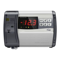
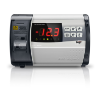
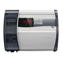
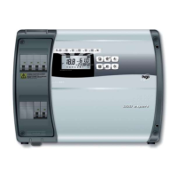
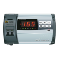
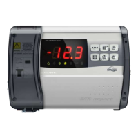
The ECP202 EXPERT + BASE electronic controller, for assembly and use, is equipped
with:
• Nr 3 seals, to be fitted between the fixing screws and the box back panel;
• Nr 1 user’s manual.
 Loading...