System 450™ Series Modular Control Systems with Standard Control Modules Technical Bulletin
17
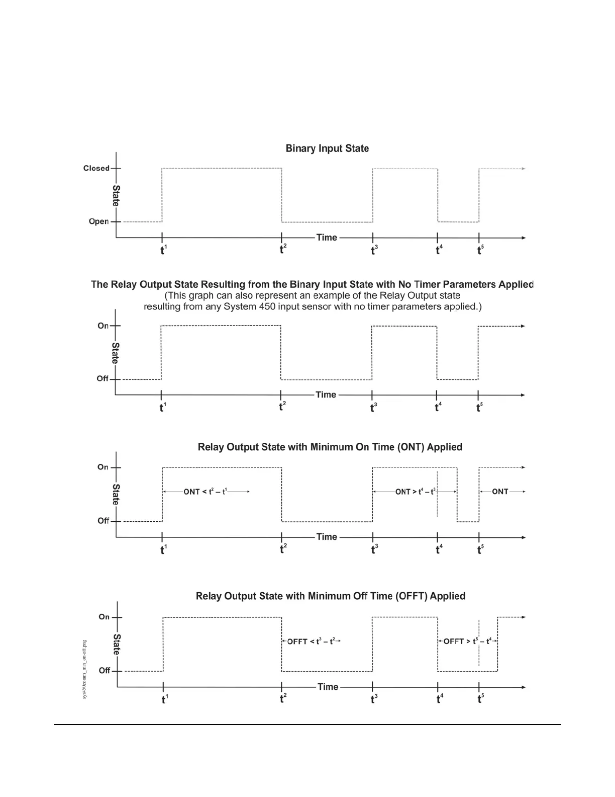
The bottom two graphs in Figure 6 show an example of the relay output behavior when the Minimum On or Off
Time parameter is applied to the relay output (regardless of whether the relay output references a binary input or
another compatible sensor).
Figure 6: Behavior of a Relay Output Referencing a Binary Input or Other
System 450 Sensor and the Resulting Output States with
the Minimum On and Minimum Off Time Parameters Applied
 Loading...

