System 450™ Series Modular Control Systems with Standard Control Modules Technical Bulletin
46
Note: The condition (temperature, pressure, or humidity), unit of measurement, minimum differential value,
default setup values, and condition value ranges available in the output setup screens are determined by
the Sensor Type for the sensor that an output references. See Table 5 on page 24 for more information on
sensors that are compatible with System 450 standard control modules, their Sensor Types, and the
values and ranges associated with each Sensor Type.
The Relay ON and Relay OFF parameters allow you to select the condition values at which the relay turns on and
turns off. The first time you access the Relay ON (ON
x
) and Relay OFF (OFF
x
) screens, the default ON and OFF
values for the referenced sensor appear.
Note: If you select a sensor (Sn-1, Sn-2, or Sn-3) that is set up as a binary input, the ON and OFF selections
screens do not appear in the Relay Output Setup screens. The relay ON and OFF state is controlled by the
binary input state. See Binary Input Control for Relay Outputs
on page 14 for more information.
The minimum differential value for the condition is determined by the Sensor Type of the sensor that an output
references. The minimum differential is fixed and is automatically enforced in the setup UI when you select ON and
OFF values. After you select the ON value, the condition values within the minimum differential range are not
available to select. See Table 5 for minimum differential ranges.
The ON Delay Time and OFF Delay Time parameters allow you to set a time (0 to 300 seconds) to delay the relay
from going On or Off after the ON or OFF value is reached. See Relay On and Off Duration Control
on page 15 for
more information.
The Minimum Relay ON Time and Minimum Relay OFF Time parameters allow you to set a minimum time (0 to
300 seconds) that the relay stays On or Off after the ON or OFF value is reached. See Relay On and Off Duration
Control on page 15 for more information.
The Sensor Failure Mode parameter allows you to select whether the output relay is on or off if the referenced
sensor encounters a sensor or wiring failure. See Sensor Failure Mode
on page 25 for more information.
To set up a relay output:
1. Access the System 450 UI and navigate to the desired Relay Output Setup Start (OUTR
x
) screen
(Figure 26). (See Accessing and Navigating the User Interface
on page 41.)
2. In the Relay Output Setup Start (OUTR
x
) screen, press to go to the Select Sensor (SENS
x
) screen. (The
Select Sensor screen does not appear here if a sensor is already selected for this output. In that case, go to
the next step.) Press or to select the hard-wired or functional sensor (Sn-1, Sn-2, Sn-3, Sn-d, HI-2, or HI-
3) that the output references. Press to save the sensor selection and go to the next screen.
3. In the Select Relay ON Value (ON
x
) screen, press or to select the temperature, pressure, or humidity
value at which the relay turns On. Press to save the ON value and go to the next screen.
Note: If you selected the Sn-d sensor in Step 2, the Select Relay Differential ON Value (dON
x
) screen is
displayed. Press or to select the temperature, pressure, or humidity differential value at which the
relay turns On. Press to save the dON value and go to next screen. (See Differential Control
on page 24
for more information.)
4. In the Select Relay OFF Value (OFF
x
) screen, press or to select the temperature, pressure, or humidity
value at which the relay turns Off. Press to save the OFF value and go to the next screen.
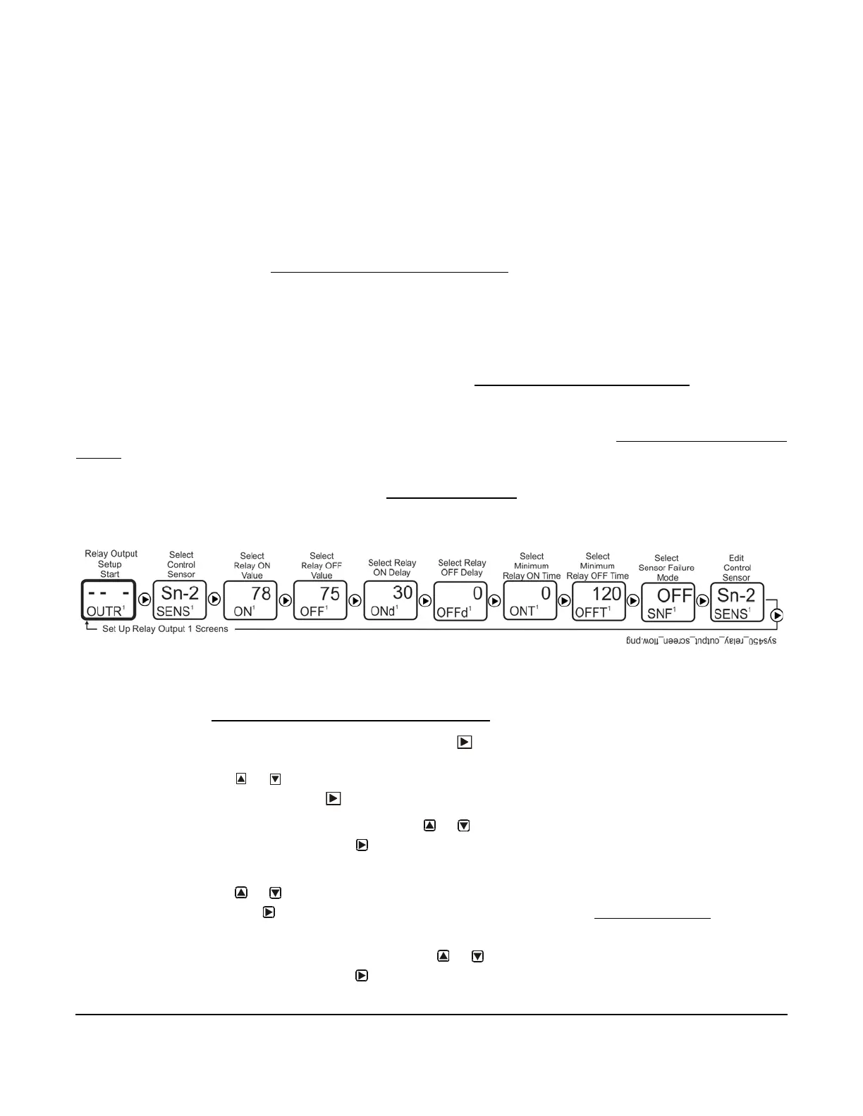
Figure 26: Relay Output Setup Start Screen and Setup Screen Flow
 Loading...

