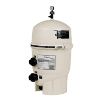
The Pentair Clean and Clear® Plus Cartridge Filter is designed for use in pool and spa circulation systems, providing efficient filtration to maintain water clarity. This filter operates under high pressure, and proper installation, operation, and maintenance are crucial for safe and reliable service, as well as to prevent severe injury, death, or property damage.
Function Description:
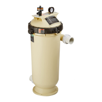
The filter utilizes cartridges to remove debris and impurities from pool or spa water. Water enters the filter, passes through the cartridge elements, and then returns to the pool or spa. The filter's large surface area is designed to maximize debris capacity, reducing the frequency of cleaning. A manual air relief valve and pressure gauge are integrated into the system to facilitate safe operation and maintenance by allowing users to relieve pressure and monitor system performance. The filter is designed to be easily plumbed with 1.5" x 2" bulkhead unions.
Important Safety Instructions:
Operating this system under high pressure requires strict adherence to safety protocols. Air can enter the system during servicing, leading to pressurization that could cause the top closure to separate with significant force. To mitigate this risk, users must always relieve pressure by opening the manual air relief valve before opening the filter or tightening the clamp bolt. Before starting the pump after servicing, it is essential to ensure the clamp band is correctly fastened.
The maximum working pressure for this filter is 50 psi. Exceeding this pressure, even during hydrostatic pressure tests, can damage the filter and lead to component failure. If the pool or spa system's operating pressure is unknown, an ASME-approved automatic Pressure Relief or Pressure Regulator should be installed and set to the lowest working pressure of any system components.
When performing hydrostatic pressure tests, it is critical to keep people away from the system, post warning signs, and establish barriers around pressurized equipment. Electrical controls (ON/OFF switches, timers, control systems) should be installed at the equipment pad, allowing users to operate, start up, shut down, or service the pump or filter without placing any part of their body over or near the pump strainer lid, filter lid, or valve closures. This setup should also provide enough space to stand clear of the filter and pump strainer lid during system startup, shutdown, or servicing.
Always disconnect power to the pool circulating system at the circuit breaker before servicing the filter and ensure the circuit is locked out or tagged to prevent accidental activation. Children should not be permitted to use this product.
Important Technical Specifications:
The filter models and their corresponding specifications are:
- CCP240: Filter Area 240 sq. ft., Flow Rate 90 GPM, Turnover Capacity (Gallons) 32,400 (6 hours), 43,200 (8 hours), 64,800 (12 hours). Required Vertical Clearance: 56" [132.1 cm].
- CCP320: Filter Area 320 sq. ft., Flow Rate 120 GPM, Turnover Capacity (Gallons) 43,200 (6 hours), 57,600 (8 hours), 86,400 (12 hours). Required Vertical Clearance: 62" [157.5 cm].
- CCP420: Filter Area 420 sq. ft., Flow Rate 150 GPM, Turnover Capacity (Gallons) 54,000 (6 hours), 72,000 (8 hours), 108,000 (12 hours). Required Vertical Clearance: 68" [172.7 cm].
- CCP520: Filter Area 520 sq. ft., Flow Rate 150 GPM, Turnover Capacity (Gallons) 54,000 (6 hours), 72,000 (8 hours), 108,000 (12 hours). Required Vertical Clearance: 74" [188 cm].
The maximum working pressure for all models is 50 psi. The filter's overall dimensions vary by model, with a consistent width of 21.5" [54.6 cm] and a base width of 23" [58.4 cm]. The height (DIM "A") ranges from 37" for the CCP240 to 56" for the CCP520.
Usage Features:
- Filter Location: The filter should be mounted on a level concrete slab, positioned to ensure instructions, warnings, and the pressure gauge are visible and readable. Adequate clearance around the filter is necessary for visual verification of clamp installation and for servicing. The manual air relief valve should be positioned to safely direct purged air or water away from electrical equipment.
- Filter Plumbing: All plumbing connections must comply with local codes. PTFE or silicone-based lubricants should be used on O-rings for union and bulkhead couplings; petroleum-based products will damage the equipment.
- Start-Up Instructions: Before starting the pump, ensure the clamp ring spring is fully compressed with coils touching. Open the manual air relief valve until it snaps into the full open position. Stand clear of the filter and start the pump. Monitor for proper operation; if pressure appears before water outflow, a solid stream of water does not appear within 30 seconds, or water leaks from the filter halves, immediately shut off the pump, relieve pressure, and troubleshoot. Once a steady stream of water appears, close the manual air relief valve. Record the "Original Starting Pressure" and the pressure at which the filter should be cleaned (approximately 10 psi higher than the original starting pressure). For variable speed pumps, record the "Original Pump RPM."
- Opening the Filter: To open the filter, shut off the pump, turn off any automatic controls, and disconnect power at the circuit breaker. Open the manual air relief valve by turning it 1/4 turn counterclockwise until it snaps into the full open position and wait until all pressure is relieved (pressure gauge must read zero psi). Open the drain plug to empty the filter. Loosen the clamp barrel nut with a 7/8-inch wrench, remove the barrel nut, spring, and washers, then remove the clamp ring. Carefully lift the filter lid, avoiding lifting by the air relief valve. Do not use screwdrivers or pry-bars to lift the lid, as this can damage the O-ring.
- Installing the Filter Lid and Clamp Ring: Ensure the O-ring is clean and properly seated on the tank bottom. Seat the filter lid onto the tank bottom. Place the clamp ring over the upper and lower tank flanges, insert the T-bolt, and hand-tighten the nut. Use a 7/8-inch socket wrench to tighten further, tapping around the clamp ring with a rubber mallet to ensure proper seating. Continue tightening until the spring coils touch. The clamp is correctly installed only when the spring coils remain touching after tapping. Close the drain plug.
Maintenance Features:
- Pressure Gauge Maintenance: The pressure gauge is a critical indicator of system operation. It should read zero psi after pressure is relieved, indicate pressure when the system is operating, and be readable and undamaged. Replace if it fails to meet these requirements.
- Manual Air Relief Valve Cleaning: To clean the valve, shut off the pump and relieve pressure. Pull out the locking tabs and unlock the valve stem and cover assembly by turning it counter-clockwise. Pull the assembly away from the valve body, remove debris, and ensure the air passage is open by inserting a 5/16-inch drill bit. Check O-rings for good condition, proper positioning, and lubrication with a silicone-based lubricant (petroleum-based products will cause damage). Reinstall the valve stem and cover assembly by pressing downwards and turning clockwise until it snaps into position.
- Filter Cartridge Cleaning: Clean the filter when the pressure gauge reads approximately 10 psi higher than the "Original Starting Pressure" or when a significant reduction in flow is noticed. After following the "Opening the Filter" instructions, remove the pump strainer basket and clean it. Remove the compression spring and spring adapter from the top manifold, then remove the top manifold itself. Carefully remove each cartridge. Use a garden hose with a straight flow nozzle, holding it at a 45-degree angle, to wash the entire cartridge from top to bottom, paying attention to the area between pleats. For pools with high perspiration, suntan lotions, or oils, soak the cartridge for at least one hour in a commercial filter cleaner, a solution of 1 cup trisodium phosphate (TSP) to 5 gallons of water, or 1 cup dishwasher detergent to 5 gallons of water. Thoroughly rinse the cartridge to remove all oils and cleaning solutions. Wash out the inside of the filter tank and bottom manifold. Inspect the gasket around the outer lip of the bottom plate. Place the bottom manifold, cartridges, and top manifold into the tank, ensuring the spring and standpipe assembly are retained on the top manifold. Ensure the O-ring is clean and seated onto the tank bottom. Follow the "Installing the Filter Lid and Clamp Ring" instructions.
- Acid Soaking Filter Cartridges: After extended operation, cartridges may require acid soaking to remove algae, calcium carbonate, iron, and other mineral build-ups. First, remove all oils and cleaning solutions from the cartridges. Wear protective equipment: rubber gloves, safety glasses, and an N-95 dust mask. Create a solution of one part muriatic acid to twenty parts water in a large plastic container, introducing the acid close to the water's surface to minimize splash. Gently place the bottom halves of the cartridges into the solution for 10 minutes or until bubbling stops, then turn them over to soak the top halves for another 10 minutes. Remove the cartridges and thoroughly wash them with a garden hose, holding the nozzle at a 45-degree angle. Reinstall the cartridges and dispose of the acid solution according to local regulations.
- Replacing Filter Cartridges: Filter cartridge elements typically last about three years under normal conditions, but life can vary based on pool conditions. To replace, follow the "Opening the Filter" instructions. Remove the compression spring, spring adapter, and top manifold. Carefully remove each cartridge. Inspect the gasket around the outer lip of the bottom plate. Install replacement cartridges onto the bottom manifold, then reinstall the top manifold, ensuring the spring and standpipe assembly are retained. Follow the "Installing the Filter Lid and Clamp Ring" instructions.