2
CLEAN AND CLEAR
®
PLUS Cartridge Filter Installation and User’s Guide
Filter Location
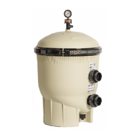
1. The lter should be mounted on a level concrete slab. Position the lter so
that instructions, warnings and the pressure gauge are visible to the
operator and readable. It also should be positioned so that the plumbing
connections, control valve and drain plug are convenient and accessible for
servicing and winterizing.
2. Be certain to install electrical controls (e.g., on/o switches, timers, control
systems, etc.) so that the user is allowed enough space to stand clear of the
lter and pump during startup, shutdown or servicing.
3. Allow sucient clearance around the lter to permit visual verication that the
clamp is properly installed around the tank anges, see FIGURE 1.
Note: See Installing the Filter Lid and Clamp Ring, page 5.
4. Allow sucient space above the lter to remove the lter
lid for cleaning and servicing. This distance will vary with
the model of lter you are using. See TABLE 2 for the
necessary vertical clearance.
5. Position the lter to safely direct water drainage away
from electrical equipment or anything that might be
damaged.
6. Position the Manual Air Relief Valve to safely direct
purged air or water (See Installing the Manual Air Relief
Valve, page 3).
RISK OF ELECTRICAL SHOCK OR ELECTROCUTION. Water discharged from an improperly positioned lter or valve
can create an electrical hazard that can cause severe personal injury as well as damage property.
Filter Plumbing
Make all plumbing connections in accordance with local plumbing and building codes. Do not use pipe joint compound,
glue or solvent on the bulkhead connections. The provided lter plumbing connections include an O-ring seal.
Use PTFE or silicone based lubricants when lubricating the O-rings on the union and bulkhead couplings. Use of
petroleum based products will damage the equipment.
INSTALLATION
This lter must be installed by a qualied pool technician in accordance with all applicable local codes and ordinances.
Improper installation could result in death or serious injury to pool users, installers, service professionals, or others and
may also cause damage to property.
For Installation of Electrical Controls at Equipment Pad (ON/OFF Switches, Timers, Control Systems and
Automation) Install all electrical controls at the equipment pad, such as ON/OFF switches, timers, control systems, etc.
to allow the operation (startup, shutdown or servicing) of any pump or lter so the user does not place any portion of his/
her body over or near the pump strainer lid, lter lid or valve closures. This installation should allow the user enough
space to stand clear of the lter and pump strainer lid during system startup, shutdown or servicing of the system lter.
FIGURE 1
MODEL
FILTER
AREA
REQUIRED VERTICAL
CLEARANCE
CCP240 240 sq. ft. 56" [132.1 cm]
CCP320 320 sq. ft. 62" [157.5 cm]
CCP420 420 sq. ft. 68" [172.7 cm]
CCP520 520 sq. ft. 74" [188 cm]
TABLE 2
 Loading...
