Do you have a question about the Pentair F783E and is the answer not in the manual?
Defines warning symbols used in the manual.
Information on export regulations for the device.
Covers dangers from high pressure and explosive atmospheres.
Addresses risks of electric shock and electrical equipment safety.
Provides the company's contact details and address.
Outlines the terms and conditions of the product warranty.
Directs users to online resources for manuals and data sheets.
Details the IECEx certification for the product.
Details the ATEX certification for the product.
Lists the conditions for safe use of the certified product.
Describes the intended use and application of the control head.
Provides an overview of the control head's features and benefits.
Details the various functions, options, and designs of the control head.
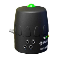
Illustrates and describes the physical components of the control top.
Shows the pneumatic circuit diagram for the solenoid valve.
Covers pneumatic connections, manual operation, and position feedback.
Details environmental and operational limits for the device.
Lists standards the device complies with and relevant directives.
Explains the information found on the device's rating plate.
Provides dimensional drawings and specifications of the control head.
Details weight, housing, and sealing materials of the control head.
Covers air supply requirements, quality, and pressure specifications.
Illustrates control head configuration on linear and rotary actuators.
Outlines safety precautions during installation.
Details procedures for mounting the control head onto an actuator.
Step-by-step guide for installing on linear actuators.
Procedure for adjusting the limit switches for proper operation.
Guide for installing on rotary actuators and setting targets.
References sections for pneumatic and electrical hookups.
Safety warnings for opening or closing the housing.
Procedure for unscrewing and opening the control head housing.
Procedure for lubricating, fitting, and tightening the housing cap.
Safety warnings related to pneumatic installation.
Details the pneumatic ports and connections on the control head.
Explains how to adjust exhaust flow restrictors for speed control.
Shows options for connecting the 24V DC or AC system.
Provides power supply and consumption details for the 24V system.
Safety warnings related to 24V DC/AC electrical installation.
Explains the input/output data flow and terminology used.
Procedure for connecting cables using a cable gland and screw terminals.
Wiring diagrams for bulkhead connector configurations.
Explains what AS Interface is and its purpose.
Shows AS-interface electrical connection types.
Details power supply and load specifications for AS-interface.
Details power usage and wiring for AS-interface connections.
Explains data flow for AS-interface modules.
Instructions for connecting AS-interface via bulkhead connector.
Procedure for AS-interface cable connection using a cable gland.
Explains the function of LED indicators on the AS-i module.
Describes the AS-i module's device profile and ID codes.
Details the configuration of input and output data bits.
Outlines the parameter bit settings for the AS-i module.
Explains the DeviceNet industrial network protocol.
Shows electrical connection options for DeviceNet.
Provides power supply and load specifications for DeviceNet.
Details power usage and internal wiring for DeviceNet.
Explains data flow for DeviceNet modules.
Instructions for connecting DeviceNet via bulkhead connector.
Procedure for DeviceNet cable connection using a cable gland.
Explains the function of LED indicators on the DeviceNet module.
Specifies the DeviceNet module's group 2 slave device type.
Describes how to read module status, alarms, and flags.
Details the output mapping and error flag reset functions.
Covers node location, analogue/counter inputs, and date representation.
Steps for installing the optional Hi-Viz indication unit.
Troubleshooting and maintenance for the Hi-Viz unit.
Safety precautions for decommissioning and dismantling.
Procedure for safely removing the F783E control head.
Guidelines for disposing of the device responsibly.
| Model | F783E |
|---|---|
| Category | Controller |
| Brand | Pentair |
| Display | LCD |
| Enclosure Rating | NEMA 3R |
| Voltage | 120/240V AC |