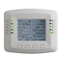
SPACOMMAND
®
Spa-Side Remote Installation and User’s Guide
8. Close the control panel and secure it with the two access screws.
9. Install the high voltage panel cover and secure it with the two retaining
screws.
10. Close the load center front door and secure with the two latches.
11. Switch power on to the load center.
12. For spa-side remote IntelliTouch control system setup information, refer to
“Adding a Spa-Side Remote to IntelliTouch automation,” on page 15.
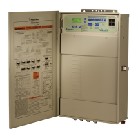
IntelliTouch control
systems personality
board COM ports
(J7/J8)
16
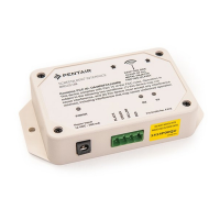
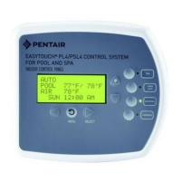
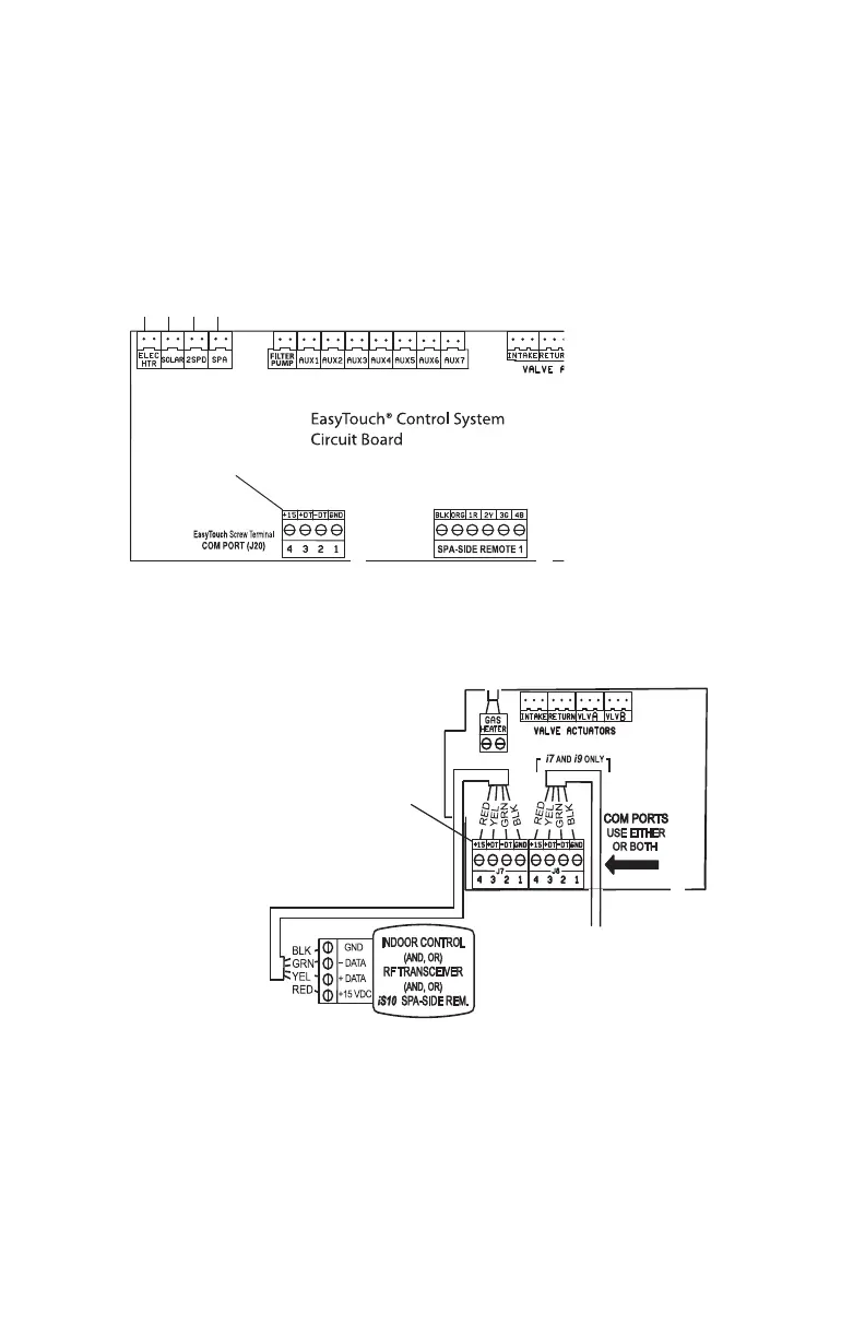
EasyTouch control system
circuit board
5. Insert the four-wire cable into the plastic grommet on the bottom of the
enclosure and route the wire up through the low voltage raceway to the main
circuit board.
6. Strip back the cable jacket one inch and the cable conductors ¼-inch.
7. EasyTouch System: Insert the wires into the COM PORT (J20) screw
terminals located on the top of the EasyTouch® Control System circuit board
(see diagram below). Secure the wires with the screws. For wiring details,
refer to the pin configuration shown below. Note: Multiple wires may be
inserted into a single screw terminal.
IntelliTouch
®
Control System: Insert the wires into the either of the COM
PORTS (J7 and J8) screw terminals located on the left side of the Personality
board. Secure the wires with the screws. For wiring details, refer to the pin
configuration shown below. Note: Multiple wires may be inserted into a single
screw terminal.
IntelliTouch control
systems personality circuit
board
COM port
 Loading...