2018-07
42
LB Remote I/O System
Installation
3.11 Strain Gauge Measurement
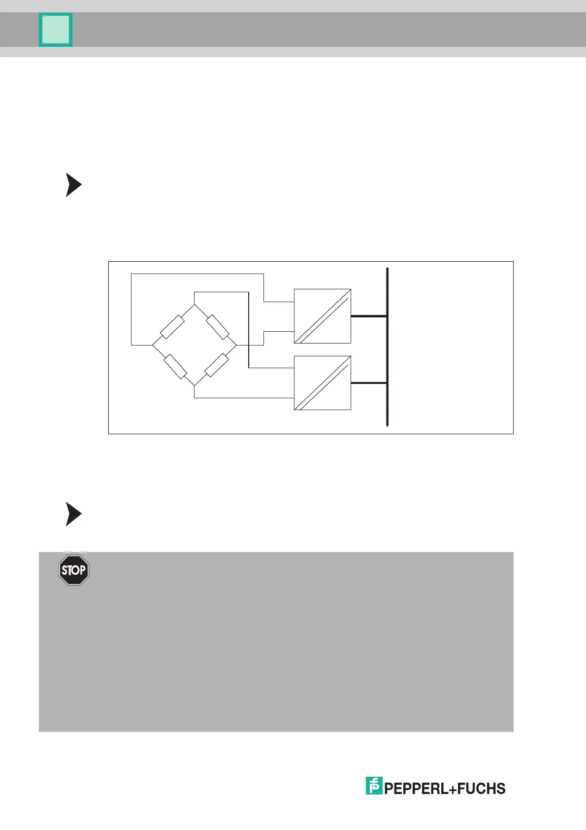
I/O modules LB4101* and LB5*02 can be interconnected for strain gauge measurements. Use
analog output LB4101* to create a constant current, and the measuring input for temperature
input LB5*02* to process the millivolt signal for the resulting bridge voltage.
A constant current of 20 mA is sufficient to power a 350- bridge. A bridge voltage of 7 V is
produced. With a bridge sensitivity of 2 mV/V, a voltage of 14 mV results at full load.
Configuring I/O Modules for Strain Gauge Measurement
1. Either set the LB4101* analog output operating mode to simulation and select 20 mA as the
simulation value, or set a fixed value of 20 mA via the fieldbus.
2. Set the LB5*02* temperature input to a millivolt measurement mV.
3. Deactivate the cold junction of temperature input LB5*02* by setting the thermostat
temperature for the external cold junction to 0 °C.
Figure 3.13 Example of a strain gauge bridge
3.12 Status Monitoring of the Output Switch-off
The I/O modules LB1001* and LB1008A enable status monitoring of the output shutdown.
Configuring I/O modules for status monitoring
Configure the I/O module as passive voltage input. Deactivate the channel supply. See to the
"LB Remote I/O System - Software" manual..
Bus5*02
4*01
+
–
2+
5 -
6 -
5+
+–
Danger!
Explosion hazard from incorrect connection!
Incorrect installation and configuration of the device may cause sparks and other hazards in
potentially explosive atmospheres that could ignite the surrounding atmospheres.
If you use the I/O module for status monitoring, configure the module as a passive voltage
input. Deactivate the channel supply.
The circuit for the output switch-off is a (non-intrinsically safe) SELV circuit. Disconnect
this circuit from other circuits according to explosion protection and electrical safety
requirements.
Keep the isolation distances between the non-intrinsically safe circuit and the intrinsically
safe circuits.
Note that the module loses its suitability for the intrinsic safety type of protection if you
connect at least one channel of the module to a non-intrinsically safe circuit.