2018-07
30
LB Remote I/O System
Installation
X2 Terminal Assignment
X2.1 = 0 V
X2.2 = + 24 VDC (SELV/PELV)
X2.3 = earth
X1 Terminal Assignment
X1.1 = 0 V
X1.2 = + 24 VDC (SELV/PELV)
X1.3 = earth
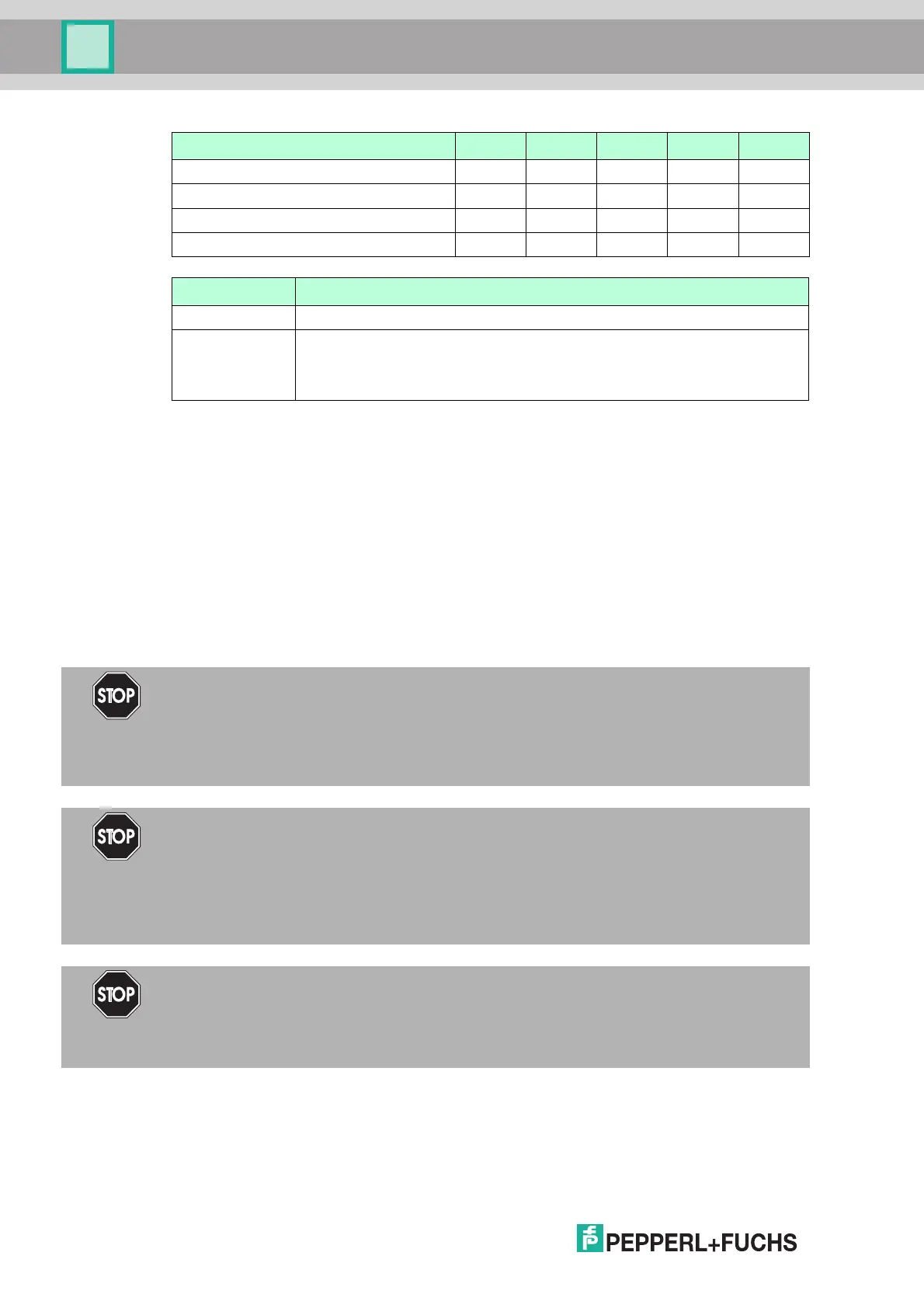
3.3.3 LB9035A
Bereich 1 2 3 4 5
Steckplätze LB9022S 3...5 6 ... 10 11 ... 15 16 ... 20 21 ... 24
Steckplätze LB9024S 25 ... 29 30 ... 34 35 ... 39 40 ... 44 45 ... 48
S1-Schalter S1.1 S1.2 S1.3 S1.4 S1.5
X3-Kontakt X3.1 X3.2 X3.3 X3.4 X3.5
S1.1 ... S1.5 Auswirkung
S1.x = ON Die Abschaltung der E/A-Module im zugehörigen Bereich ist deaktiviert.
S1.x = OFF Die Abschaltung wird im zugehörigen Bereich durch den zugehörigen X3-
Kontakt gesteuert. Wenn der X3-Kontakt offen ist (X3.x = OFF), werden die
E/A-Module mit Abschalteingang für den zugehörigen Bereich
abgeschaltet.
Danger!
Risk of explosion
Accessories such as plugs and terminators that do not meet the requirements for use in
hazardous areas can cause explosive mixtures to ignite.
Only use accessories approved for use in the respective environment.
Danger!
Risk of Explosion
Connecting and disconnecting from circuits such as terminals, plug-in jumpers or terminators
can ignite potentially explosive mixtures.
Connecting and disconnecting from circuits is permitted only when not located in a potentially
explosive atmosphere.
Danger!
Risk of Explosion
Actuating the operating elements can ignite potentially explosive mixtures.
Only actuate the operating elements when not located in a potentially explosive atmosphere.