2018-07
34
LB Remote I/O System
Installation
X1 Terminal Assignment
X1.1 = 0 V
X1.2 = + 24 VDC (SELV/PELV)
X1.3 = earth
3.4
Inserting and Removing Modules
Fix
ed slots are reserved on the backplane for com units and power supplies. Com units are
equipped with mechanical coding pins on the underside of the enclosure to prevent these
modules from being accidentally plugged into the slot of an I/O module.
Slots for I/O modules have equal status, meaning functions can be arranged side by side as
required. I/O modules with intrinsically safe circuits and I/O modules with non-intrinsically safe
circuits can also be arranged side by side. Please note that a clearance of 50 mm must always
be maintained between intrinsically safe and non-intrinsically safe circuits. To ensure this
clearance is maintained, fit a separation wall between modules with intrinsically safe circuits
and modules with non-intrinsically safe circuits.
Unused slots can be left empty or covered using place-holder modules LB9099 and LB9199A.
Installing I/O Modules
1. Arrange the I/O modules on the backplane from left to right.
2. Push the I/O module into a vacant slot on the backplane.
3. Separate I/O modules with intrinsically safe circuits and I/O modules with non-intrinsically
safe circuits using a separation wall. See chapter 3.5
4. Make a note of the types of module used or other identification codes on the label carrier
above the I/O modules.
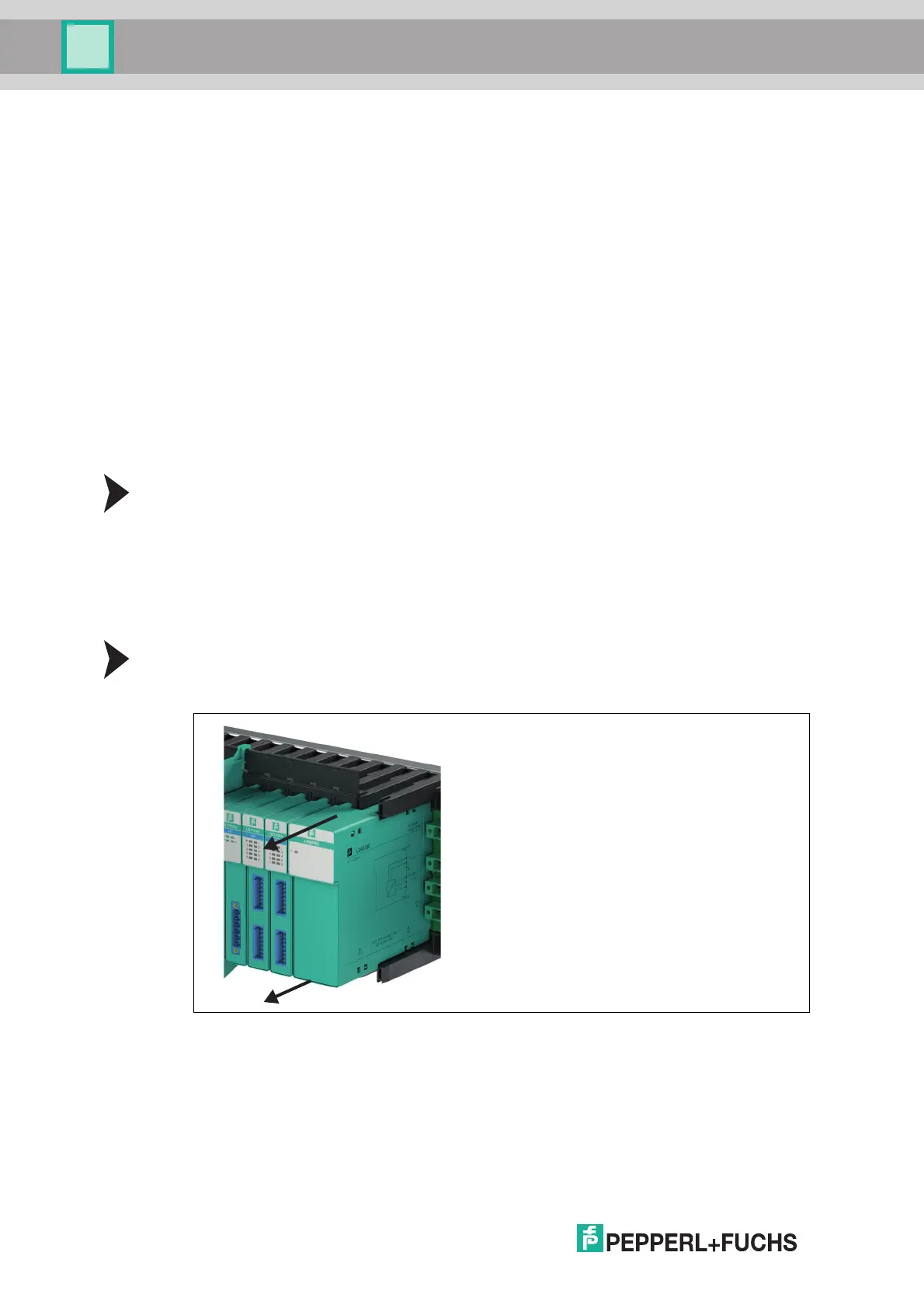
Removing I/O Modules
1. Remove the modules by positioning your thumb and index finger on the top and bottom of
the module and pulling.
Figure 3.11 Removing modules
2. If necessary, adjust the information on the label carrier above the I/O modules.