LB Remote I/O System
Installation
2018-07
47
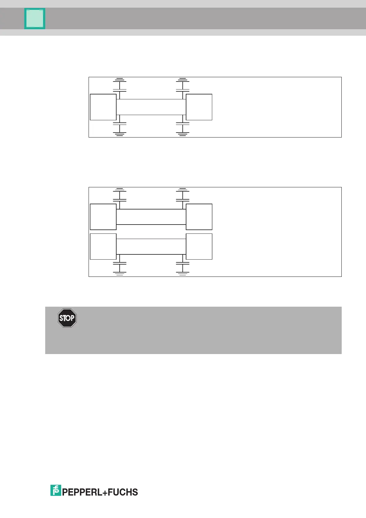
EMC filters are used in many devices to divert any interference to ground. For the sake of
symmetry, all lines are provided with suitable capacitance. Capacitively coupled high-
frequency interference is effectively canceled out by the symmetrical layout.
Figure 3.19 EMC filters in signal paths
The same applies to galvanically isolated signals. However, unexpected results may arise in
networks created by multichannel systems without isolation. This is because the filter
capacitors may even run in parallel, depending on the setup. Isolate the channels to eliminate
any interference.
Figure 3.20 EMC filters in a network (simplified diagram)
3.15.2 Wiring
Lay the signal leads such that they are separate from the power cables. Please note that AC
voltages and current spikes can induce stray voltages in neighboring lines. Thus, shielded
cables should be used for EMC-tested devices.
Grounding bars can be laid separately from the shielding (see IEC/EN 60079-14). The
shielding is then grounded at one point.
Danger!
Risk of explosion from improper installation
Improperly installed lines can lead to ignition of explosive mixtures.
Observe the installation regulations according to IEC/EN 60079-14 for laying cables in
hazardous areas.