2018-07
46
LB Remote I/O System
Installation
Terminators
The fieldbus must have exactly two terminators per segment, one at the start and one at the
end. A segment usually starts at the master, while the last remote I/O station is taken to be the
end of the segment. A segment also ends or begins at a repeater or a fiber optic cable.
A bus with 3 segments, 1 master, a fiber optic cable transfer path, 4 nodes, and 1 repeater has
6 terminators (T).
Master(T) — Node — (T)Fiber optic cable(T) — Node — (T)Repeater(T) — Node — (T)Node
The terminator depends on the line type, as specified in DIN EN 61158 and DIN EN 61784. A
distinction is made between:
R = 220 for line type A (< 12 MBaud)
R = 150 for line type B (< 0.5 KBaud). Where possible, line type B should no longer be
used.
R = 120 for service bus
3.15 Potential Equalization and Shielding
3.15.1 Interference
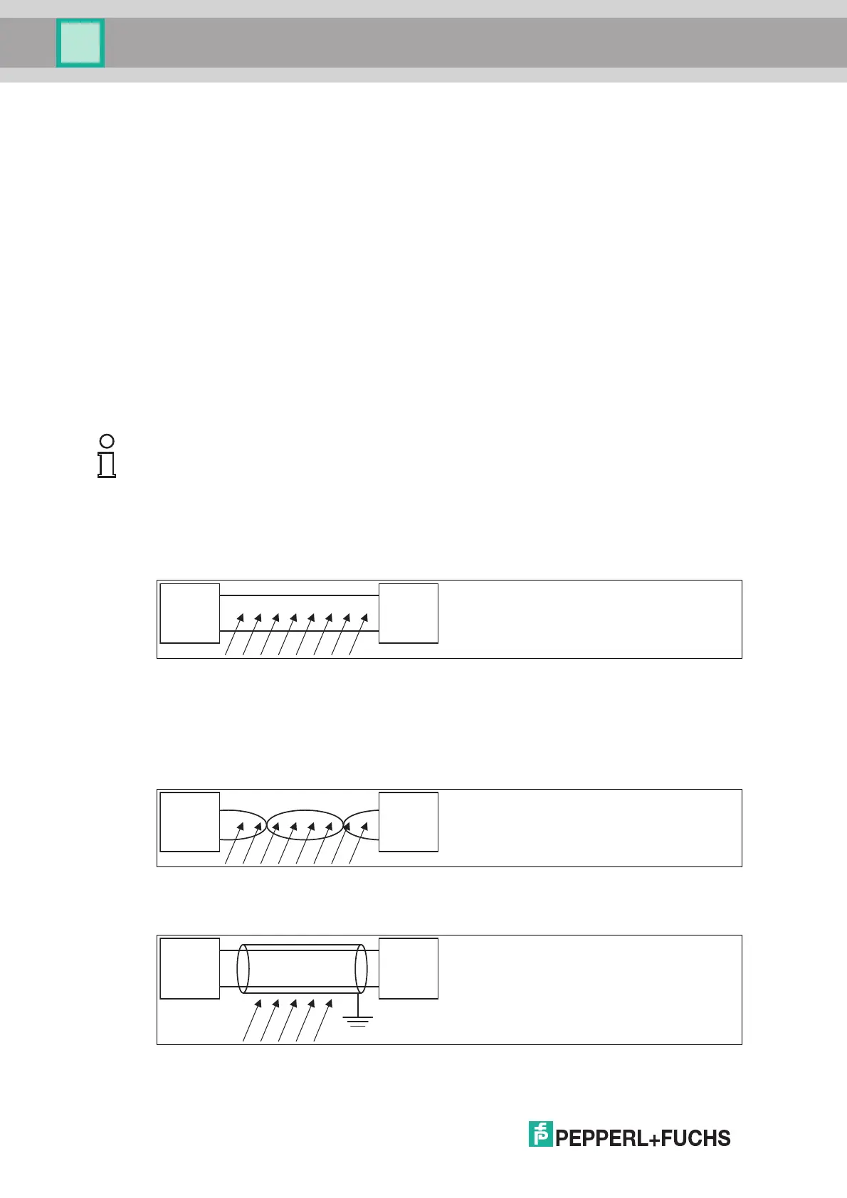
Electromagnetic fields can interfere with the communication path.
Figure 3.16 Interfering signals caused by induction in parallel conductors
Twisted-pair cables significantly reduce the influence of these interference fields, particularly
when compared to cables with parallel strands. The direction of the recorded interference field
in a twisted-pair cable reverses over short intervals. This means that the induced interference
is practically canceled out, while in parallel strands the interference is active across the entire
area.
Figure 3.17 Reduced admission of interfering signals in twisted-pair cable
A shielding keeps interfering signals away from the communication path.
Figure 3.18 Shielding prevents the entry of interference fields
Note!
The following subchapters cannot provide the reader with a complete picture of all
requirements in terms of grounding, shielding, and lightning protection. More information on
this topic can be found in the technical literature and the applicable standards.