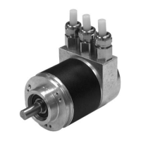
Absolute rotary encoder P**58
Manufacturer specific encoder classes
Subject to reasonable modifications due to technical advances. Copyright Pepperl+Fuchs, Printed in Germany
Pepperl+Fuchs Group • Tel.: Germany +49 621 776-0 • USA +1 330 4253555 • Singapore +65 67799091 • Internet http://www.pepperl-fuchs.com
Date of issue 01/15/04
20
5.1.4 Activate commissioning mode
Bit 2 in Octet 26 represents a switch for "commissioning mode". Commissioning mode
is a special state of the device in which additional parameters beyond the Preset value
can be transferred to the rotary encoder. When commissioning mode is activated, you
can perform "TEACH-IN", a form of programming in which the gear factor can be
determined by moving the system directly. In this mode (recognisable by the flashing
green LED) the direction of rotation and scaling set during projecting are ignored.
Instead of them, values stored internally in EEPROM are used.
The device can also be operated long term in commissioning mode. We recommend,
however, that you transfer the parameters determined in commissioning mode to
projecting and then use the device in normal mode. (This makes it possible to replace
the device without having to perform TEACH-IN again).
For a detailed description of commissioning mode, please refer to section 5.3.
5.1.5 Reduced diagnostics
For many PROFIBUS masters, the full number of diagnostic bytes (standard
diagnostics: 57 bytes) may lead to problems. Often older masters in particular cannot
work with the full number of diagnostic bytes. With rotary encoders, there is the
possibility of reducing the number of diagnostic bytes generated by the rotary encoder
to 16. If "Class 1" is selected as the device class, only 16 diagnostic bytes will be
generated.
5.1.6 Software limit switches
Two positions can be programmed. If the value falls above or below these limits
respectively, the absolute encoder sets Bit 27 to "1" in the 32-bit actual process value.
The bit is set to "0" between these two positions. Both limit switch values can be set
as desired with parameter assignment, but they must not exceed the value of the
"Overall resolution" parameter. Limit switches are activated via Bits 5 and 6 in
Octet 26.
Octet 26 Bit 2 Commissioning mode
0 turned off
1 turned on
Octet 26 Bit 3 Diagnostic data length
0 standard = 57 bytes
1 reduced = 16 bytes
Octet 26 Bit 5 Lower limit switch
0 turned off
1 turned on
Octet 26 Bit 6 Upper limit switch
0 turned off
1 turned on

 Loading...