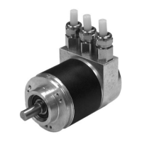
Absolute rotary encoder P**58
Manufacturer specific encoder classes
Subject to reasonable modifications due to technical advances. Copyright Pepperl+Fuchs, Printed in Germany
Pepperl+Fuchs Group • Tel.: Germany +49 621 776-0 • USA +1 330 4253555 • Singapore +65 67799091 • Internet http://www.pepperl-fuchs.com
Date of issue 01/15/04
23
5.2 Data exchange in normal mode
For manufacturer specific encoder classes P+F 2.1 and P+F 2.2, the actual process
value is transferred as a 32-bit value (double word). In addition to 25 bits that are used
for the position value, another 7 bits are used as status bits. The master sends the
Preset value to the rotary encoder along with the control bits in the (periphery) output
double word.
The current speed value is transferred as well in an additional (periphery) input word
in device class P+F 2.2:
The meanings of the status bits in the input double word are as follow:
Identifier F1 hex D0 hex
Enc. → Master status + actual position value speed
status + 2
24
2
23
... 2
16
2
15
... 2
8
2
7
... 2
0
2
15
... 2
8
2
7
... 2
0
Master → Encoder Preset value + control bits
control + 2
24
2
23
... 2
16
2
15
... 2
8
2
7
... 2
0
Bit 28 Bit 27 Bit 26 Bit 25 Meaning
ready for operation
0 = rotary encoder not ready for operation
1 = rotary encoder ready for operation
operating mode
0 = commissioning mode
1 = normal mode
software limit switch
0 = lower limit switch = actual value = upper limit switch
1 = actual value > upper limit switch or actual value <
lower limit switch
direction of rotation
0 = rising clockwise (as seen facing the shaft)
1 = rising counterclockwise (as seen facing the
shaft)

 Loading...