68 SEBU8191-01
Maintenance Section
Speed Sensor - Clean/Inspect
Environmental Factors
Ambient tempe
ratures – The engine may be
exposed to extended operation in extremely
cold environments or hot environments. Valve
components ca
n be damaged by carbon buildup if
the engine is frequently started and stopped in very
cold temperatures. Extremely hot intake air reduces
engine perfo
rmance.
Quality of the air – The engine may be exposed
to extended
operation in an environment that is
dirty or dusty, unless the equipment is cleaned
regularly. Mud, dirt and dust can encase components.
Maintenanc
e can be very difficult. The buildup can
contain corrosive chemicals.
Buildup – C
ompounds, elements, corrosive
chemicals and salt can damage some components.
Altitude
– Problems can arise when the engine is
operated at altitudes that are higher than the intended
settings for that application. Necessary adjustments
should be
made.
Incorre
ct Operating Procedures
•
Extended operation at low idle
•
Frequent hot shutdowns
•
Operat
ing at excessive loads
•
Operating at excessive speeds
•
Operating outside the intended application
Incorrect Maintenance Procedures
•
Exten
ding the maintenance intervals
•
Failure to use recommended fuel, lubricants and
cool
ant/antifreeze
i02461940
Spee
d Sensor - Clean/In spect
(Engine Speed Sensor and
Overspeed Sensor)
Wh
en the engine is cranked, small metal particles
are produced. These particles will contaminate the
magnetic end of the crankshaft position sensor and
th
e overspeed sensor. Contamination will distort
the signals that are produced by the sensors. The
sensors should be regularly cleaned and adjusted in
o
rder to ensure a good signal.
Table 24
Required Tools
Tool
Part
Number
Part Name Qty
A SE253 Crankshaft Turning Tool 1
Engine Speed Sensor
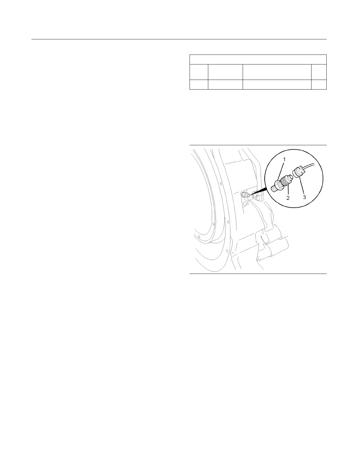
The crankshaft position sensor is located in the right
hand side of the flywheel housing.
1. Isolate the electrical supply to the engine.
g01237852
Illustration 66
Typ ical example
2. Remove the connection (3). Loosen the locknut
(1).
3. Remove the sensor (2).
4. Use a soft, dry cloth in order to clean any debris
from the sensor (2).
Note: Do not use a wire brush in order to clean the
sensor. Do not use abrasive material in order to clean
the sensor.
5. Install Tooling (A). Use Tooling (A) in order to
rotate the engine. Rotate the engine in order to
align a tooth on the ring gear with the center of
the tapped hole.
6. By hand, carefully install the sensor (2) until light
contact is made with the ring gear.
Note: Do not tighten the sensor.