4
36 User’s Handbook, TSL 4230, Issue 4
4016-E61TRS
Preparation for equalising bridge pieces and setting valve clearances
Special requirements
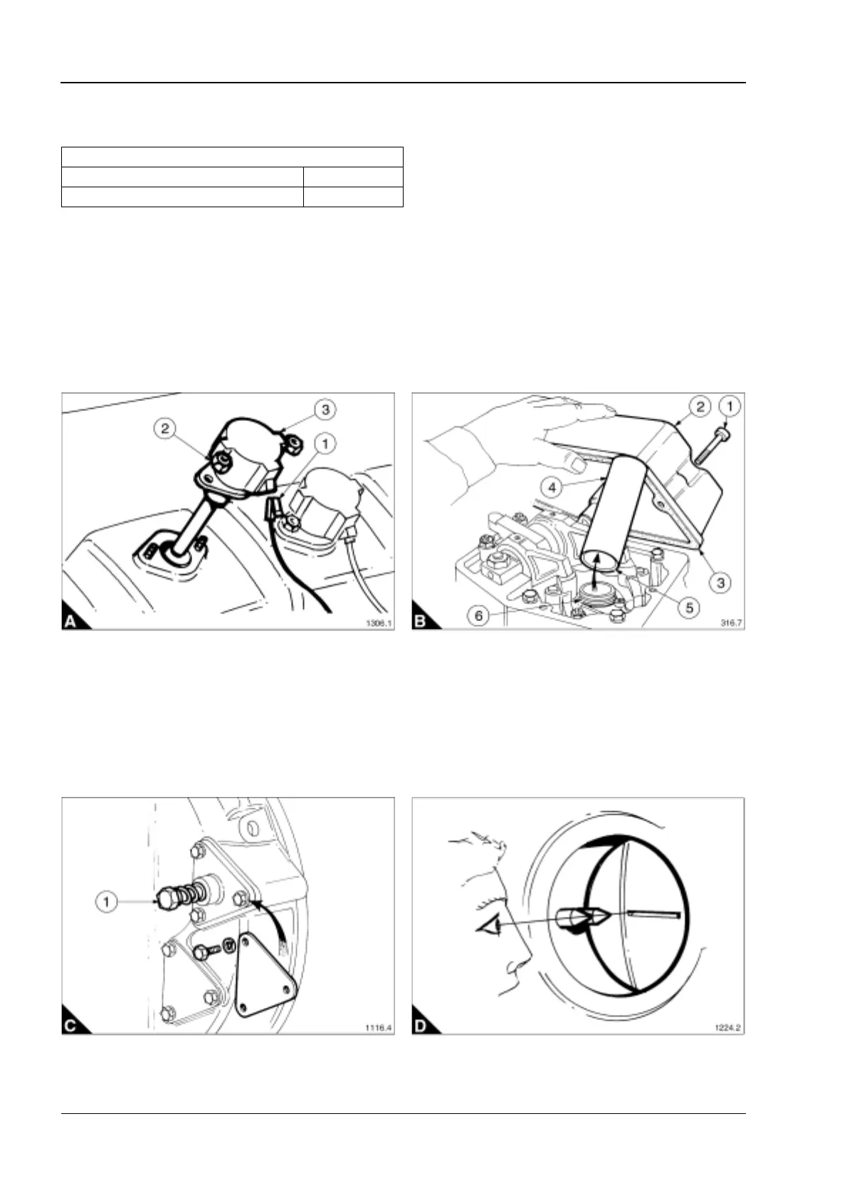
1 Disconnect the power lead (A1) from the ignition coil.
2 Remove the two retaining nuts (A2).
3 Pull the combined ignition coil/plug cap (A3) out of the rocker cover.
4 Remove the four retaining capscrews (B1) from each rocker cover (B2).
5 Lift off the rocker cover, remove and discard the gasket (B3).
6 Pull the spark plug cover tube (B4) out of the cylinder head.
Warning! When refitting the spark plug tube (B4), the internal chamfer (B5) must be fitted against the ‘O’ ring
(B6).
7 To rotate the engine to the positions required for this procedure fit the engine cranking device to the spare
starter motor mounting in the flywheel housing (C).
8 Using a socket and ratchet wrench press against the spring loaded bolt head (C1) until the pinion engages
with the flywheel gear, then crank the engine to the desired position. Refer to "Bridge piece and valve
clearance setting sequence" on page 37.
9 The engines flywheel is marked giving the T.D.C. (top dead centre) position of each cylinder. They are
viewed through an inspection hole in the flywheel housing. To get an accurate reading line up by eye the tip of
both pointers with the marks on the flywheel (D).
Special tools
Description Part number
Engine cranking device SE253
This document has been printed from SPI². Not for Resale