4
User’s Handbook, TSL 4230, Issue 4 37
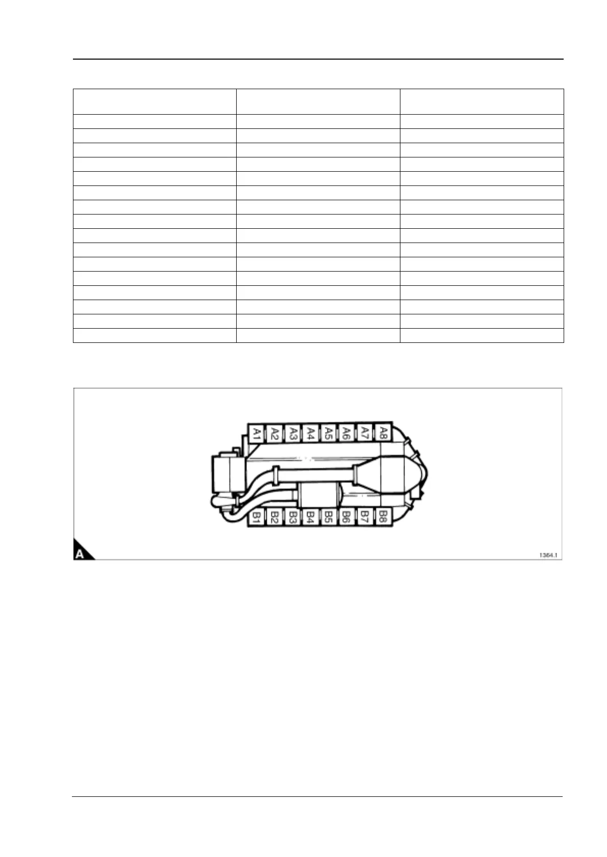
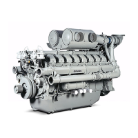
4016-E61TRS
Bridge piece and valve clearance setting sequence
Note: Where reference is made to ‘A’ and ‘B’ banks of cylinders: ‘A’ bank is to the left and ‘B’ bank is to the
right when viewed from the front of the engine, the crankshaft damper/turbocharger end.
T.D.C.
(Top Dead Centre)
Valves rocking on cylinder No.
Set bridge piece and valve
clearance on cylinder No.
A1 - A8 A8 A1
B1 - B8 B8 B1
A3 - A6 A6 A3
B3 - B6 B6 B3
A7 - A2 A2 A7
B7 - B2 B2 B7
A5 - A4 A4 A5
B5 - B4 B4 B5
A1 - A8 A1 A8
B1 - B8 B1 B8
A3 - A6 A3 A6
B3 - B6 B3 B6
A7 - A2 A7 A2
B7 - B2 B7 B2
A5 - A4 A5 A4
B5 - B4 B5 B4
This document has been printed from SPI². Not for Resale