Owner´s Manual Permobil C500 Design and Function
28
Electrical system
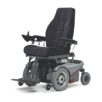
Circuit Breaker
Permobil C500 is equipped with a 63A (C500) or 80A (C500s) automatic Circuit
Breaker, which can be reset after having been triggered. It also functions as a
battery isolator and is controlled (ON/OFF) via the lever located above the left
battery cover.
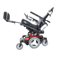
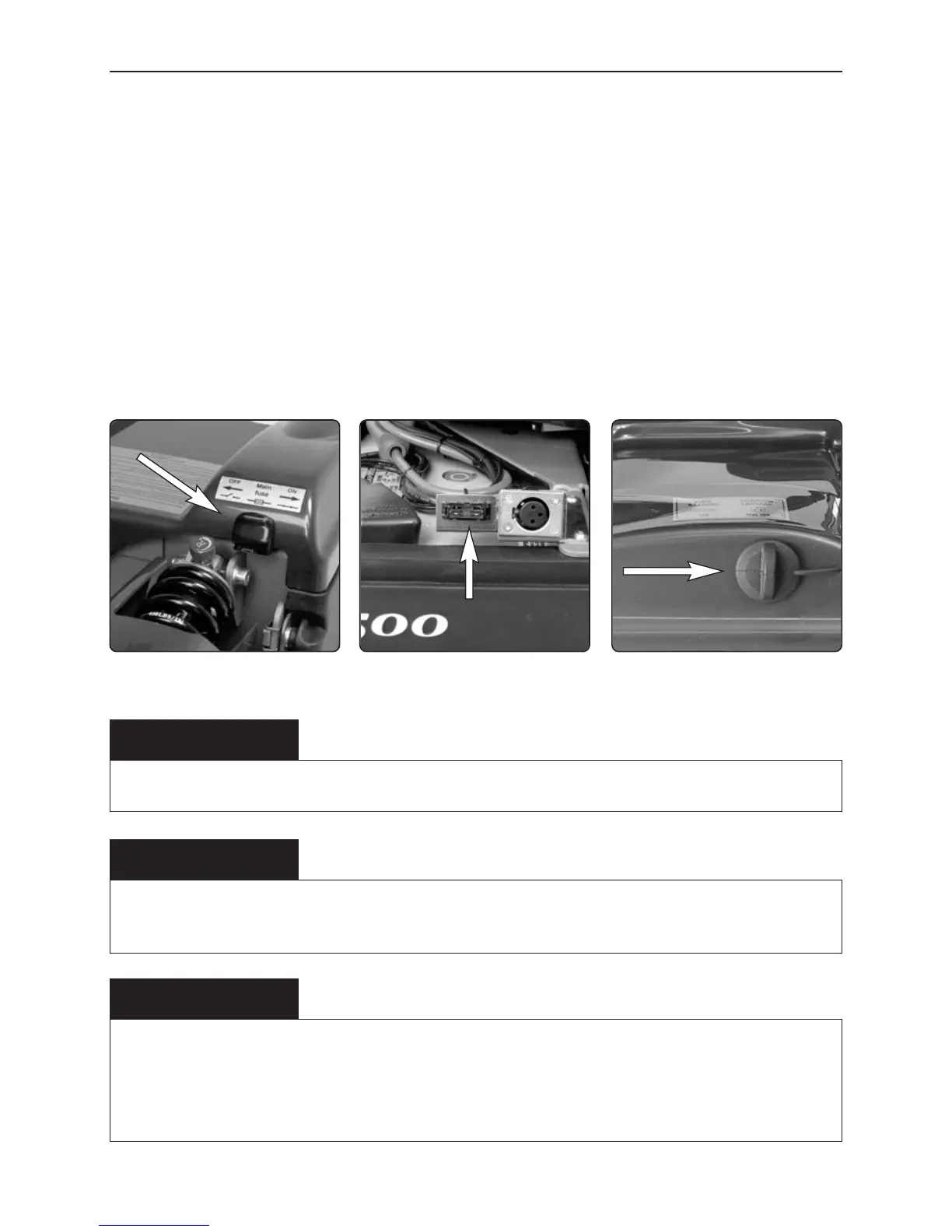
Charging Fuse 15A/Charging Socket
The Charging Fuse is located under the rear chassis cover and the Charging
Socket is located in an cutout up on the right side at the rear end of the chassis
cover and is covered by a rubber protection.
WARNING
A triggered automatic Circuit Breaker can indicate larger electrical faults. The cause should be
checked carefully before the circuit breaker is reset. Always contact an authorized serviceman or
Permobil when in doubt.
NOTE
Always shut off the Power Supply on the Control Panel before switching off the Circuit Breaker.
Charging Fuse 15A Charging Socket
WARNING
Always shut off the Power Supply on the Control Panel before changing the Charging Fuse. The
battery charger must not be connected when the Charging Fuse is replaced.
A triggered Charging Fuse can indicate a problem or defect with batteries, charger, charger cables
or the wheelchair's charging socket.
The cause of a triggered Charging Fuse should be carefully checked before the fuse is replaced.
Lever for automatic
Circuit Braker