Adjustment
11 - 2
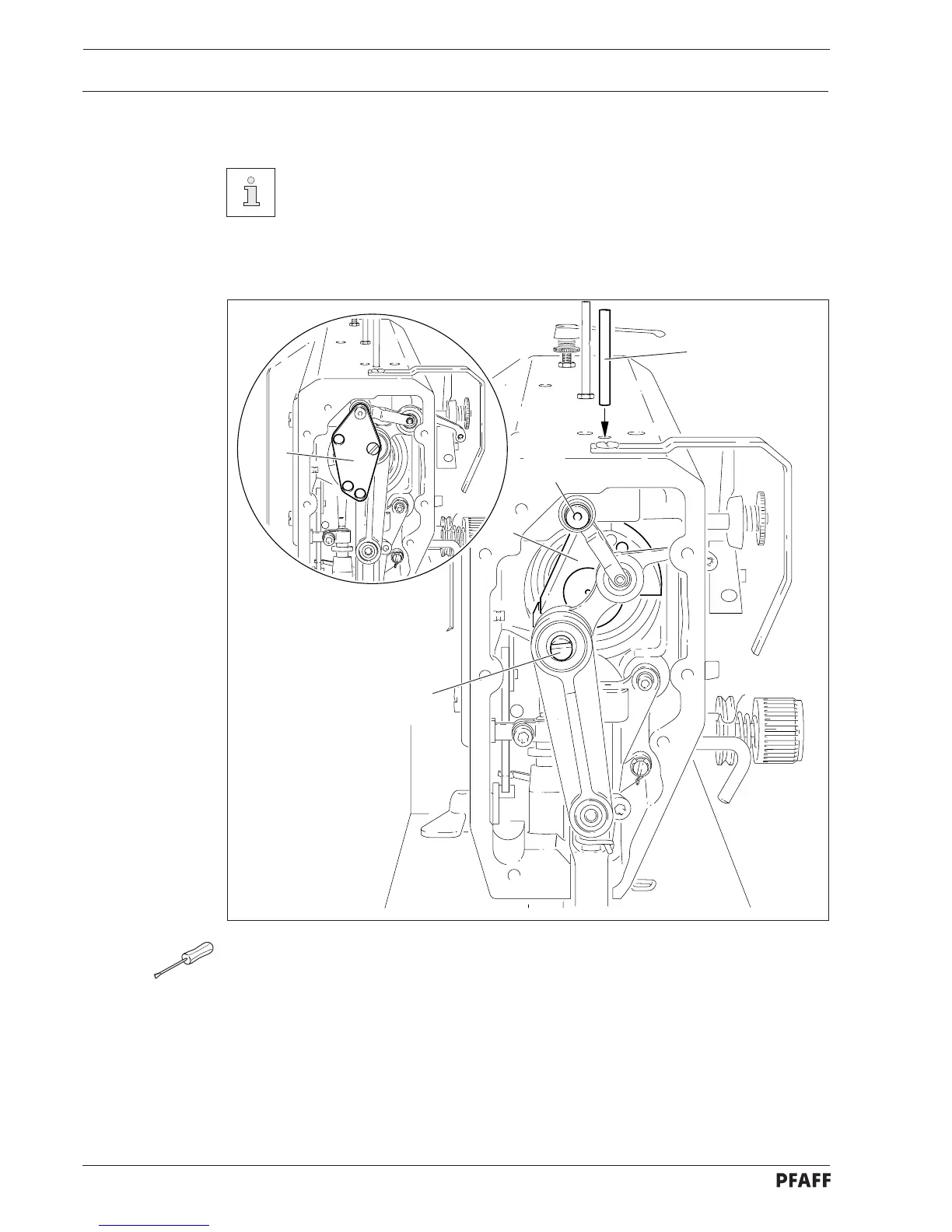
11.04 Checking and adjusting aids
With the help of the adjustment pin 1 (Part No. 13-033 346-05) and the
adjustment gauge 3 (Part No. 61-111 639-70), the required positions for the
adjustment can be set.
Setting the needle bar position 1.8 mm above BDC (needle rise position):
● Turn handwheel until the needle bar is approx. in the required position.
● Insert the adjustment pin 1 into the hole.
● Move the handwheel back and forth slightly until the adjustment pin 1 engages the
crank 2.
Setting the needle bar position 0.6 mm below TDC (feed motion timing):
● Fit adjustment gauge 3 onto bolts 4 and 5, ensuring that the right side (for 32 or 36 mm
needle bar stroke) is used.
Fig. 11 - 01
1
2
4
5
3