ENG
Operating Manual | Attachment and Installation Cooling Units | Standard Controller (SC) – 230 V | 086100113 21/66
3.6 Signs and symbols on the unit
The signs and symbols attached to the unit must be observed.
The signs and symbols attached to the unit must not be removed and must be kept in a fully legible condition. Damaged or
illegible signs and symbols must be replaced.
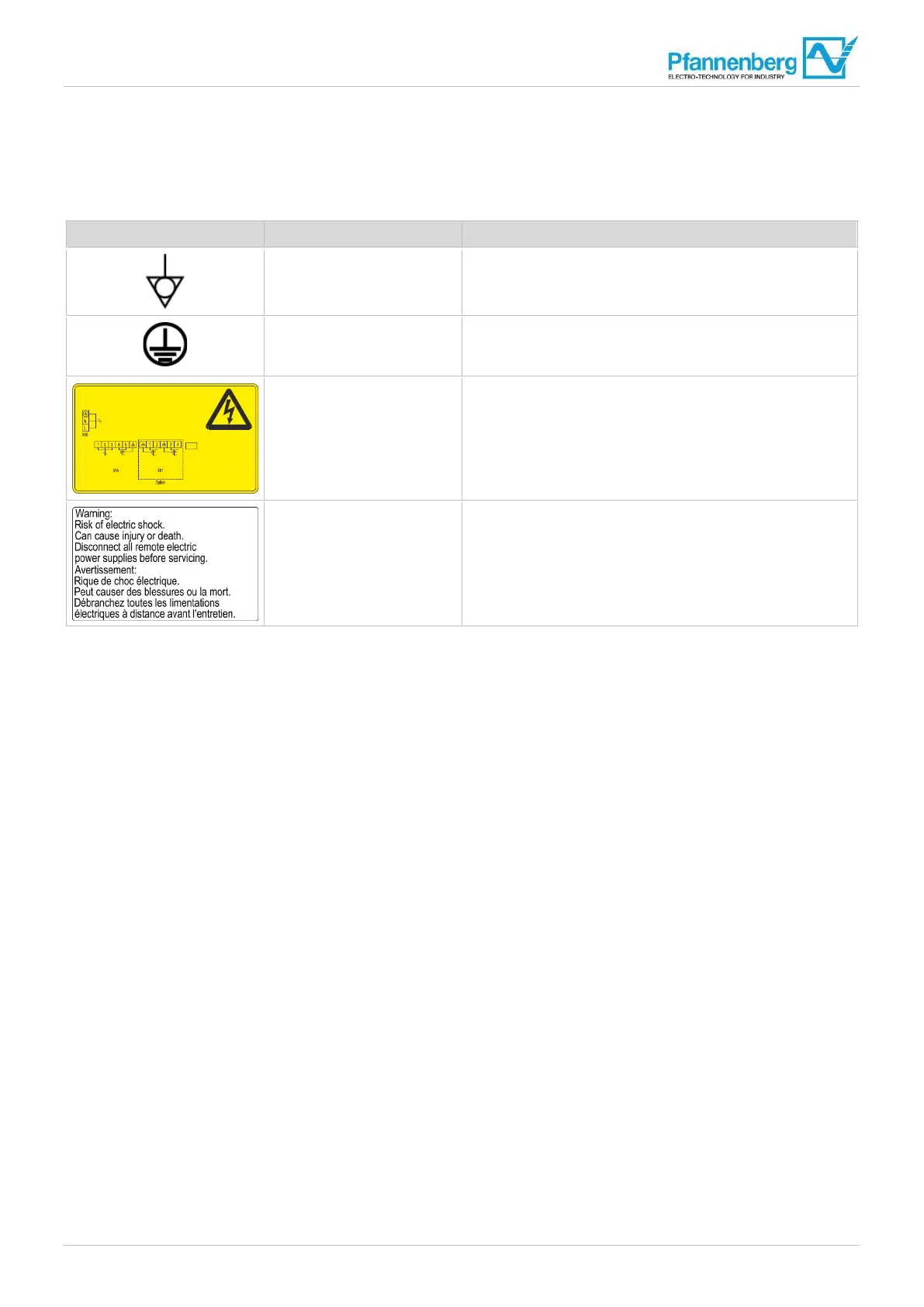
Sign/Symbol Position Description
Rear of unit at the connection
for the function equipotential-
bonding
Functional equipotential-bonding for a signal reception with
low interference between the unit and the switch cabinet.
Rear of unit at the connection
for the protective
equipotential-bonding
Protective equipotential-bonding for the connection of metal
components and dissipation of a possible touch voltage.
Rear of unit Connection diagram
Warning – Disconnect power before opening the unit
X51 – connection terminals Multimaster input/output
X54 – connection terminals door contact and fault indication
X50 – connection terminals mains supply
Rear of unit, cover of the
connection terminals
Warning – Danger of electric shock. Switch off power to the
unit before working on the unit.
Tab. 4: Signs and symbols on the unit
3
max. 2,5mm²/
AWG 14
085170888 1 1189-954
Interface
Schnittstelle
max. 2,5mm² / AWG 14
1,2 Multimaster
Ei ngang /
i nput /
en trée
2
3
2
max. 2,5mm² / AWG 14
1-3 Störmeldung /
F ault signal/
Si gnalement
d 'un incident
4,5 Türkontakt /
D oorc ontact /
C ontact de porte
3,4 Multimaster
Ausgang /
o utput /
sor tie
2
Netz/
mains/
tension
Vord em Öffnen desG erätesN etzsteckerz iehen.
Entladungsphase von 5 Minutender elek trischen
Komponenten abwarten /
Before opening disconnect mains.
Wait forun loadingphase of 5 minutes f or the electic
components /
Avant d'ouvrirl 'appareilr etirez lafi nchemâle.
Attendent la phase de déchargement de 5mi nutes
pour lesc omposantsél ectriques
Nicht unterS pannung ein-oder auss tecken/
Dono t in orunpl ugunder v oltage/
Nep ascouper l 'éléctricités oud tension