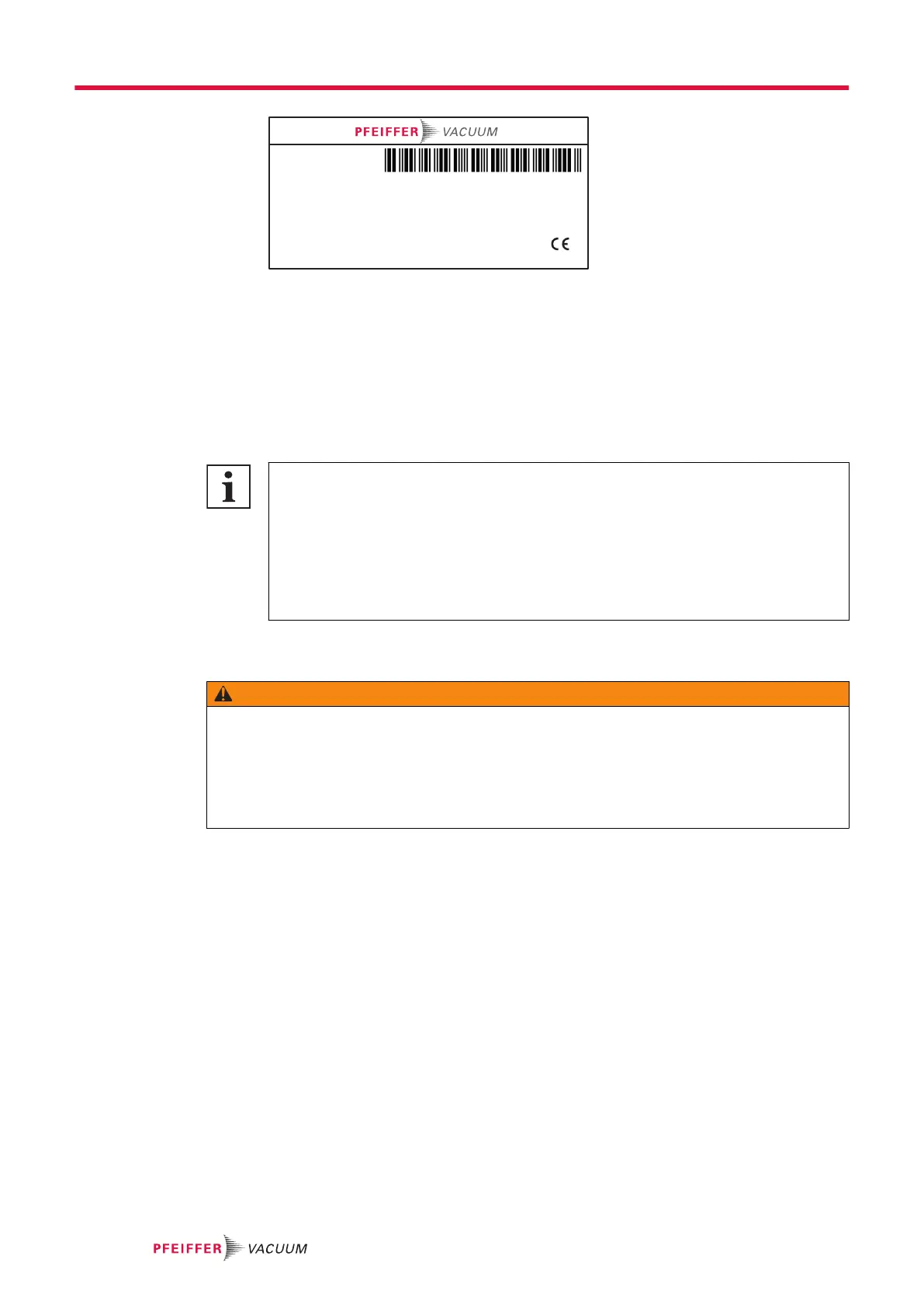
F-74000 ANNECY
S/N:FC15000123
P/N:119678
Calibration date...: 15-Jan-2015
Lost per year........: 2 %
Temperature........: 23°C
Temperature coeff: 3 %
Value..:
1,3E-7 mbar.l/s ± 10 %
1,3E-8 Pa.m
3
/s ± 10 %
HELIUM CALIBRATED LEAK
Example of calibrated leak rating plate
3. Perform a calibration on the detector.
Tightness test after calibrated leak maintenance
►
Open the calibration valve to carry out the test.
►
Spray a light flow of Helium 4 around the calibrated leak.
–
leak rate measured < 1 · 10
-8
mbar·l/s (1 · 10
-9
Pa·m
3
/s).
5.8 Analyzer cell maintenance
Pollution of vacuum circuit components
During maintenance operations for vacuum circuit components, avoid any contamination
which could subsequently result in the degassing of the parts. Special caution must be ex-
ercised to ensure cleanliness. To avoid this:
●
Perform the maintenance in an appropriate area (clean, dust-free and ventilated).
●
Use non-woven materials.
●
Dust the parts with filtered dry air (unless otherwise stated).
●
Wear unpowdered vinyl gloves (clean room gloves).
5.8.1 Analyzer cell disassembly/reassembly
WARNING
Risk of burns in case of contact with hot surfaces
For the operator’s safety, the products are designed to avoid thermal risk. However, specific operat-
ing conditions may exist that require extra caution on the part of the operator due to the high temper-
atures (surfaces > 70 °C for parts inside the cover(s)).
►
Wait for the product to fully cool down before working on it.
►
Protective gloves must be worn in accordance with standard EN ISO 21420.
Prerequisite conditions for the analyzer cell disassembly
1. Make an air inlet on the vacuum circuit (see chapter “Air inlet before a maintenance operation”).
2. Remove the cover (see chapter “Cover disassembly/reassembly”).
Service - Maintenance
18/36