PG DRIVES TECHNOLOGY S-DRIVE - INSTALLATION
SK76745/10
If you are using an Analogue 12V Status Indicator, it is must be connected between pin 10 and 0V.
For each connection and indicator type the controller will require programming to suit. The parameter that will require adjustment
is Status Output.
This will require programming to one of the following:
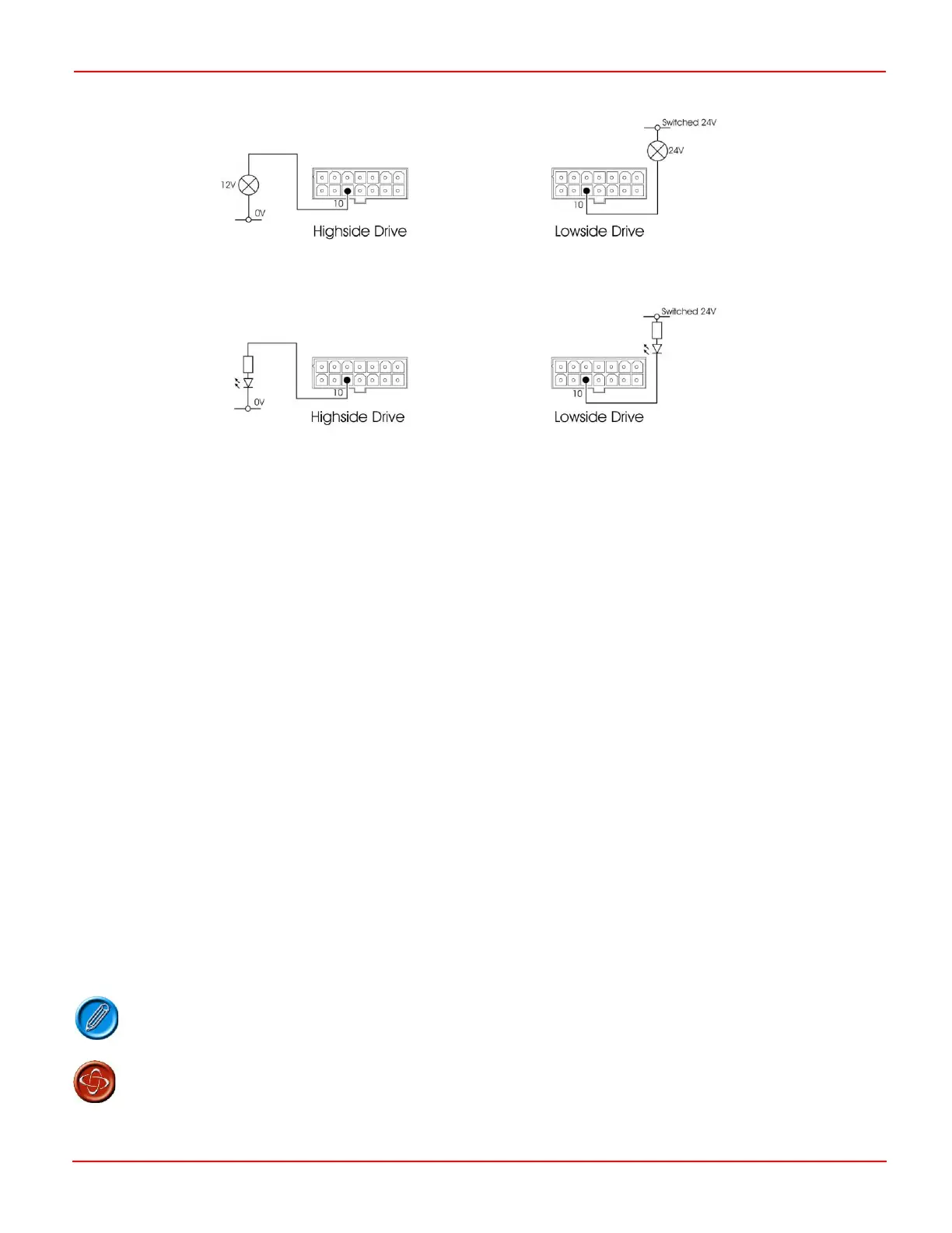
TruCharge - Suitable for Lamp and LED Status Indicators on Highside Drive connections and the TruCharge Status
Indicator.
Sink - Suitable for Lamp and LED Status Indicators on Lowside Drive connections.
Analogue - Suitable for Analogue 12V Status Indicator.
4.5.1 Status Indicator Diagnostic setting
For each Status Indicator type the controller will require programming to suit. The parameter that will require adjustment is
Diagnostic Flash Sequence.
This will require programming to one of the following:
0 - No diagnostic indication.
1 - PGDT diagnostic information. Refer to Chapter 1 section 8.
2 - Suitable for Lamp or LED Status Indicators. The Status Indicator will flash the equivalent message of the
TruCharge display.
3 - Alternative twin flash repeated code sequence.
4 - Alternative single flash repeated code sequence.
Refer to Chapter 3 for details.
4.6 24V
Pin 7 is a battery positive supply for the tiller. This pin has a current rating of 5A making it suitable as a lighting circuit supply and to
pass charging current. A suitably rated fuse must be fitted as close to pin 7 as possible.
The S200A has an internal, 3.75A self-resetting fuse.
The scooter manufacturer must install a suitable fuse to protect the scooter’s wiring. Failure to
comply with this could result in a fire hazard. PGDT accepts no liability for losses of any kind
arising from failure to comply with this condition.