S-DRIVE - INSTALLATION PG DRIVES TECHNOLOGY
SK76745/10
At no time should the current passing through pin 7 of S-Drive Scooter Controller exceed the 5A
current rating. Failure to comply with this could result in a fire hazard. PGDT accepts no liability
for losses of any kind arising from failure to comply with this condition.
This connection should have no external capacitance connected to it, and care should be taken not
exceed the fuse rating if lights or other auxiliary functions are connected.
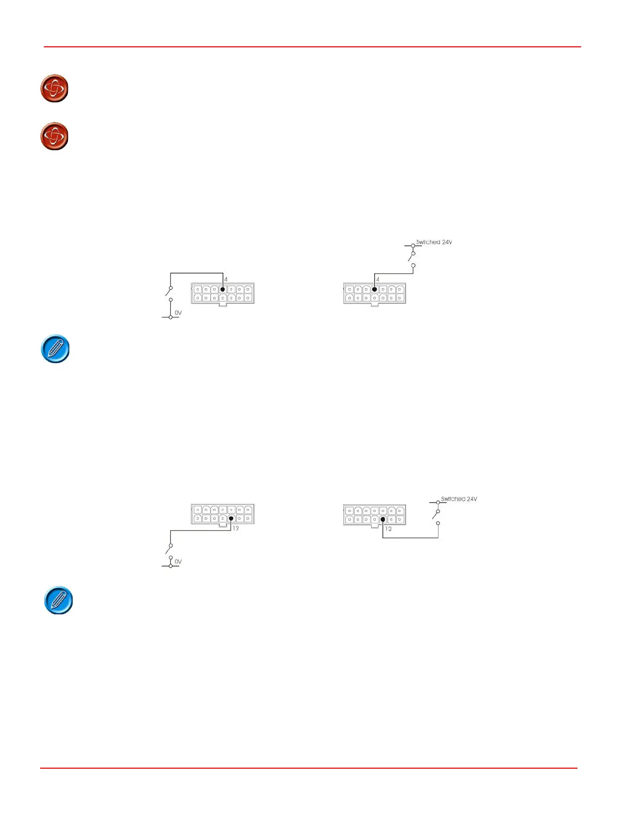
4.7 Slow/Fast Switch
Pin 4 is an input that can be used to limit the forward and reverse speeds, the forward and reverse acceleration and the forward
and reverse deceleration of the scooter. Typical uses are: to select between indoor or outdoor use or, as is a requirement in
certain countries, to limit the scooter’s speed while driving on the sidewalk.
It is possible to connect the switch to Switched 24V or 0V.
If pin 4 is connected to 0V or switched 24V the controller will drive using the programmed slow speeds and rates. Refer to the
chapter 3 for details.
If pin 4 is open then the controller will drive using the programmed fast speeds and rates. Refer to the chapter 3 for details.
4.8 Reverse Switch
Pin 12 is a connection to a reverse switch. This is required to select reverse drive only if the controller is being used with Single-
ended or Unipolar throttle configurations.
It is possible to connect the switch to switched 24V or 0V.
The polarity of the input is programmable and can be changed using the Invert Throttle parameter refer to chapter 3 for details.
With Invert Throttle set to Off, the drive will be in reverse if pin 12 is connected to 0V or switched 24V.
With Invert Throttle set to On, the drive will be forwards if pin 12 is connected to 0V or switched 24V.
4.9 Audible Alarm
Pin 3 is an output for a 24V sounder which can operate when the scooter is being driven in reverse. The positive terminal of the
sounder should be connected, via the on/off switch, to battery positive. The negative terminal of the sounder should be
connected to pin 3.