23 | P a g e
The total number of changed parameters, and the current index of changed parameters,
will be displayed at the top of the screen. If there are no changed parameters, then “No
Changed Parameters” will be shown.
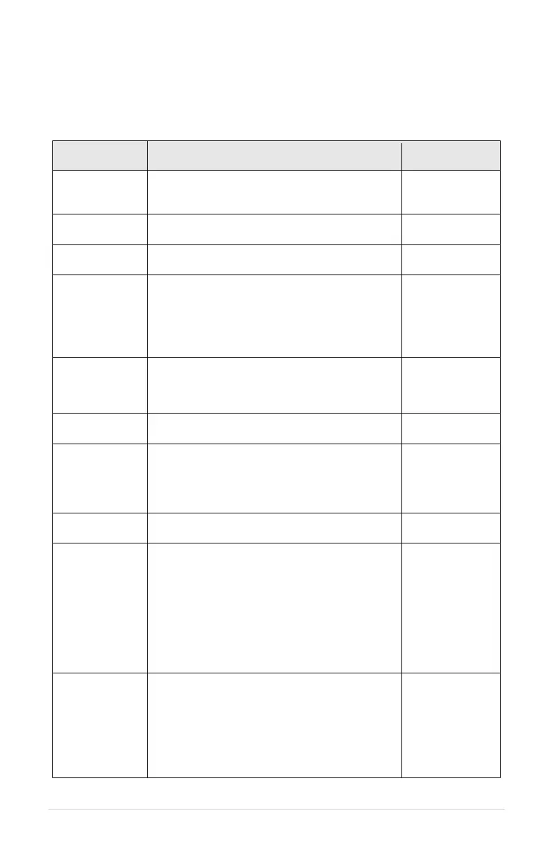
Table 12 – Operating Parameters
Maximum frequency allowed, or target frequency
at start-up ramp. This parameter value cannot be
set lower than MINIMUM FREQ.
Minimum output frequency allowed except during
startup ramp.
Used to select 2-wire or 3-wire motor.
Select the motor manufacturer to optimize
performance. When “Franklin” is chosen, the
drive will be compatible with motors containing
BIAC switches.
Default: Franklin
Pentek
Grundfoss
Other (Prompted
to select MOTOR
PHASE ANGLE)
For 3-wire drives only when “OTHER” is selected
for MOTOR MANUFACTURER. Use this to
select PHASE ANGLE based on motor specs.
Adjust PHASE ANGLE to reach desired torque.
Based on MOTOR
MANUFACTURER
/120/180
Time in seconds of linear ramp from MIN
FREQUENCY to MAX FREQUENCY.
Time in seconds from MAX FREQUENCY to MIN
FREQUENCY. Ramp time is linear. Factory
default setting enables the COAST TO STOP
parameter which disables the SHUTDOWN
RAMP parameter.
Setting for motor overload protection, Trip Class
10 curve.
DRY WELL
CURRENT
(Undercurrent
Setpoint)
Drive faults when output current goes below the
set value (dry well protection).
To use this function for dry well protection, make
certain the parameter DRY WELL KW is set at
zero.
Note: Fluctuating voltage can change motor
currents without any change in power
consumption. It may be more accurate to use the
parameter DRY WELL KW for drywell protection.
DRY WELL KW
(Underpower
Setpoint)
Drive faults when output measured in KW goes
below the set value (dry well protection).
Generally more accurate than DRY WELL
CURRENT.
To use this function for dry well protection, make
certain the parameter DRY WELL CURRENT is
set at zero.