40 | P a g e
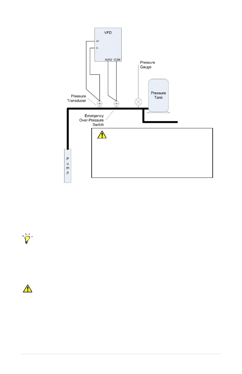
Figure 20 – Analog Constant Pressure One-Line Diagram
7.6 Basic Analog Constant Pressure Installation Procedures:
1. Install the analog pressure transducer and emergency over-pressure switch in the
water line
Control Tip: Turbulence near pressure switch or transducer can result in poor
pressure control. For best results, pressure switches and transducers should be placed at
least 6 inches away from pressure tanks, check valves, and pipe elbows.
2. Remove protective rubber boot from the over-pressure switch, insert factory provided
duplex cable through the boot, and connect a twisted pair of wires to the normally
closed (NC) and common (C) terminals of the switch
CAUTION: The use of shielded cable is recommended. Regular wire may induce
capacitance in the line and corrupt the signals from the pressure switches.
3. Attach the cable shield to the Control Terminal Ground post located next to the Control
Terminals. See Figure 6 for terminal locations.
4. Connect the emergency over-pressure limit switch to the AUX2 Control Terminal and
COM (common).
CAUTION: Operating the system in
MANUAL mode on the keypad overrides
signals from the pressures switches.
Operating the system in this mode may
lead to dangerous pressures in closed
plumbing systems