7 | P a g e
Figure 5 – Essential Series Conduit Locations
3.9 Control Wiring
WARNING! When the drive is turned OFF using a control switch connected
to the AUX terminals, dangerous voltage may still be present on the input lines and
elsewhere inside the enclosure.
The output of the drive can be controlled with a switch connected between the AUX1 and
COM terminals and/or the AUX2 and COM terminals. When AUX1 to COM and AUX2 to
COM are closed, the drive enters run mode after a delay of approximately three seconds. If
AUX1 and AUX2 are closed when the unit is powered on, the output is energized after a
delay of approximately 16 seconds. When AUX1 or AUX2 to COM are open, the drive is
stopped.
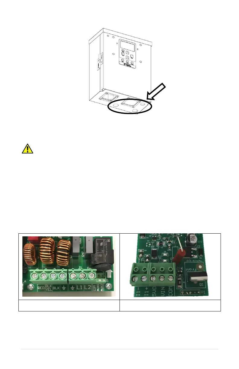
To use a 0-5 VDC transducer or a 4-20 mA analog transducer, the optional analog I/O
board is required. Contact Phase Technologies if this upgrade is needed. Figure 6 shows
control terminal locations.
b. Analog control terminals, located on
optional analog I/O board.
Figure 6 – Control Terminal Locations
Table 6 describes the control wiring terminals. See connection diagrams in Figure 7,
Figure 8, and Figure 9.