10 | P a g e
4-20 mA Analog Transducer (Available with optional analog I/O board)
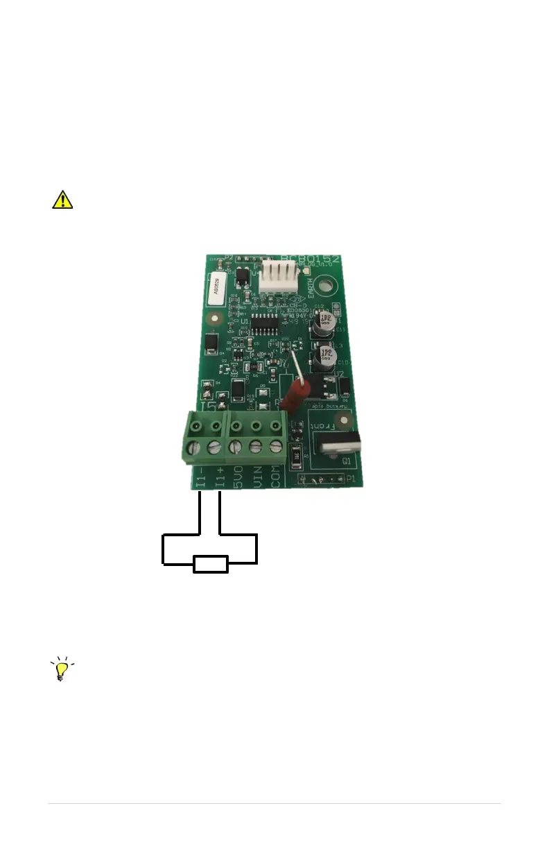
Follow these steps to connect a 4-20 mA transducer:
1. Using the keypad, set the value of parameter SYSTEM CONFIG to 2. See Section
6.5, System Configuration, and Section 7, Constant Pressure Systems, for more
information.
2. Connect the positive lead of the transducer to terminal I_1+.
3. Connect the negative lead of the transducer to terminal I_1-.
CAUTION: If the I+ and I- sensor cable is short circuited or if the sensor fails, the
drive will stop and indicate a fault, SENSOR CONNECTION FAIL. Disconnect input power
to the drive and fix the short circuit or replace the sensor.
Figure 8 – Connection Diagram for 4-20 mA Analog Transducer
Control Tip: Turbulence near pressure switch or transducer can result in poor
pressure control. For best results, pressure switches and transducers should be placed at
least 6 inches away from pressure tanks, check valves, and pipe elbows.