11 | P a g e
0-5 VDC Potentiometer (Available with optional analog I/O board)
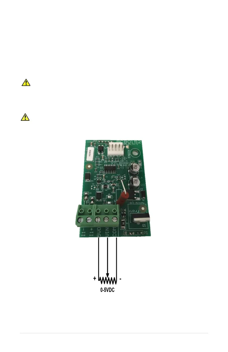
Follow these steps to connect a 0-5 VDC potentiometer:
1. Using the keypad, set the value of parameter SYSTEM CONFIG to 3. Refer to Table
14, Interface Parameters, or Section 6.5, System Configuration, for details.
2. Connect the negative lead of the potentiometer to control terminal COM
3. Connect the wiper terminal of the potentiometer to the V IN terminal
4. Connect the positive lead of the potentiometer to the 5 VO terminal.
CAUTION: By default, AUX1 is programmed such that OPEN=STOP, CLOSED=RUN
and AUX2 is programmed such that OPEN=RUN, CLOSED=STOP. When SYSTEM
CONFIG = 2 (Analog CP), AUX1 and AUX2 are programmed such that OPEN=RUN,
CLOSED=STOP. See parameters AUX1 SELECT and AUX2 SELECT to change this
setting.
CAUTION: The resistance value of the transducer must be from 5k Ohms to 2k
Ohms. Resistance below 5k Ohms will produce a high current in the circuit and may
damage components in the circuit.
Figure 9 – Connection Diagram for 0-5 VDC Potentiometer