8 | P a g e
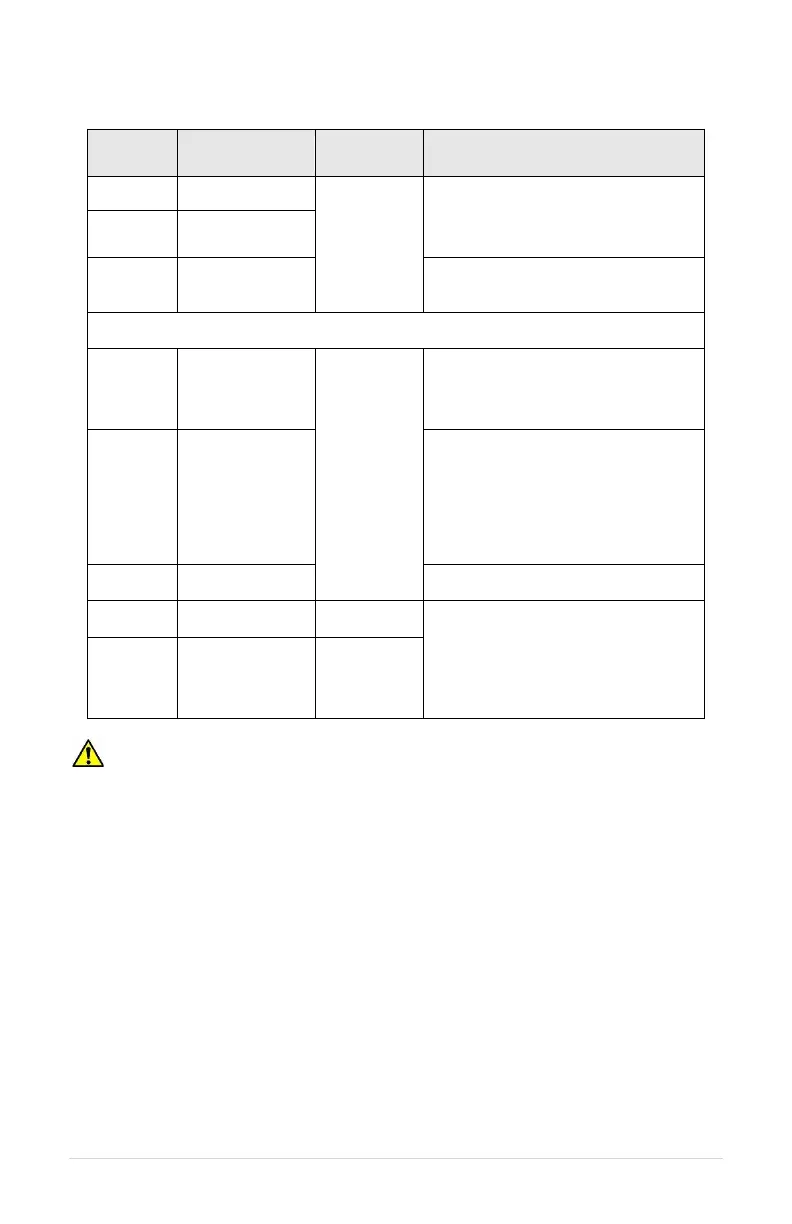
Table 6 - Control Terminal Ratings and Descriptions
Dry contact
type
Pullup
Voltage
< 5 volts,
galvanically
isolated
Digital input. Commonly used for
RUN/STOP command. Controlled by
parameters AUX1 SELECT and
AUX2 SELECT.
Common for AUX terminals.
The following terminals are only available with upgraded I/O board.
5 VDC supply to provide power to a
potentiometer. Refer to Table 14 for
details. See Figure 9 for connection
diagram.
Analog input for motor speed control.
Speed is relative to scale of signal
from 0 Hz to Max Frequency, set in
Adjustable Parameter menu (default
60 Hz). Connect the wiper terminal of
a potentiometer to this terminal as
shown in Figure 9.
Analog transducer connection for
analog constant pressure or
proportional motor speed control from
a current source. Refer to Table 14
for details. See Figure 8 for a
connection diagram.
CAUTION! Electrostatic discharge (ESD) can damage electronic components.
Discharge ESD prior to touching the board or to making connections. To discharge ESD,
touch your hand to unpainted metal on the enclosure.