Do you have a question about the Phcbi MCO-18AC Series and is the answer not in the manual?
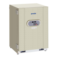
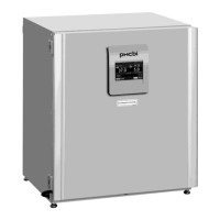
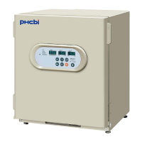
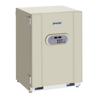
The PHCbi MCO-18AC Series CO2 Incubator is a laboratory instrument designed for cell culture, providing a controlled environment for optimal cell growth. It maintains precise temperature and CO2 density, with optional UV sterilization and advanced contamination prevention features.
The MCO-18AC Series CO2 Incubator creates a stable and sterile environment for cell cultures. It precisely controls chamber temperature and CO2 density, crucial for various biological applications. An optional UV system (MCO-18UVS3) is available to sterilize the humidifying pan water and circulating air within the chamber, enhancing contamination prevention. The incubator is equipped with a control panel and keypad for setting and monitoring parameters, as well as an alarm system for safety and self-diagnosis. It also supports automatic CO2 cylinder changeover with an optional MCO-21GC gas auto changer.
Product Name: CO2 incubator MCO-18AC External Dimensions: W620 mm x D710 mm x H900 mm (W24.4 inch x D28.0 inch x H35.4 inch) Internal Dimensions: W490 mm x D523 mm x H665 mm (W19.3 inch x D20.6 inch x H26.2 inch) Interior Volume: 170 L (6.00 cu.ft.) Exterior Material: Painted steel Interior Material: Stainless steel containing copper Outer Door: Painted steel Inner Door: Tempered glass Trays: 3 trays made of stainless steel, W450 mm x D450 mm x H12 mm (W17.7 inch x D17.7 inch x H0.47 inch), Maximum load: 7 kg/tray Access Port: Inner diameter: 30 mm (1.18 inch), on the back side Insulation: Rigid polyurethane foamed-in place Heating System: DHA system (heater jacket + air jacket system) Heater Power: 282 W Humidifying System: Natural evaporation with humidifying pan Temperature Controller: PID control system Temperature Display: Digital display CO2 Controller: ON-OFF control system/TC sensor CO2 Density Display: Digital display Air Circulation: Fan assisted Air Filter: 0.3 µm, Efficiency; 99.97 % or more Temperature Control Range: Ambient temperature +5 °C to 50 °C (ambient temperature; 5 °C to 35 °C) Temperature Distribution: ±0.25 °C (ambient temperature; 25 °C, setting; 37 °C, CO2 5 %, no load) Temperature Variation: ±0.1 °C (ambient temperature; 25 °C, setting; 37 °C, CO2 5%, no load) CO2 Control Range: 0% to 20% CO2 Variation: ±0.15% (ambient temperature; 25 °C, setting; 37 °C, CO2 5 %, no load) Chamber Humidity: 95%R.H.±5%R.H. Heat Emission: Max. 1116 kJ/h Applicable Environment Condition: Temperature: 5 °C to 35 °C, Humidity: equal or less than 80 %R.H. (Designed performance may not be obtained when ambient temperature is equal or less than 15 °C) Noise Level: 24 dB (A scale) Power Consumption: Max. 300 W (MCO-18AC-PT), Max. 310 W (MCO-18AC-PK, MCO-18AC-PE) Rated Voltage, Frequency: AC 110 V-120 V, 60 Hz (MCO-18AC-PT), AC 220 V, 60 Hz (MCO-18AC-PK), AC 220 V-240 V, 50 Hz (MCO-18AC-PE) Amperage: Max. 2.6 A (MCO-18AC-PT), Max. 1.4 A (MCO-18AC-PK, MCO-18AC-PE) Remote Alarm Contacts: Allowable contact capacity: DC 30 V, 2 A CO2 Inlet Connection: 4 mm to 6 mm (0.157 inch to 0.236 inch) diameter tube can be connected CO2 Inlet Pressure: 0.03 MPa(G) (0.3 kgf/cm²(G), 4.4 psi(G)) Accessories: 3 trays, 3 sets of tray support, 1 gas tube, 1 humidifying pan, 1 pair of stacking plate A and B, 2 protective stickers, 2 tube bands Weight: 92 kg Optional Accessories: UV system set (MCO-18UVS3), Gas regulator (MCO-010R), Tray (MCO-47ST) including 2 tray supports, Half tray (MCO-25ST), Gas auto changer (MCO-21GC), Roller base (MCO-170RB), Interface board (MTR-480), Interface board (MTR-L03) (*Only for the Data acquisition system MTR-5000 user.)
Installation: The incubator must be installed on a sturdy, level floor in a well-ventilated indoor environment, away from direct sunlight, heat sources, and high humidity. It should not be installed near water sources or where corrosive/flammable gases are present. Proper grounding is essential to prevent electric shock. Connecting a CO2 gas cylinder requires confirming the gas type, using a regulator with specified pressures (0.03 MPa(G) secondary pressure), and ensuring secure, leak-free connections. Adequate ventilation or CO2/O2 densitometers are recommended due to the risk of oxygen depletion.
Contamination Prevention: To minimize contamination, the incubator should be placed in a clean environment, ideally a cleanroom. Users should avoid locations with high temperatures, humidity, or drafts. Clean containers and trays should always be used. The chamber must be kept clean, wiping off fingerprints and condensation. Sterile distilled water is required for the humidifying pan; ultrapure water should not be used. The incubator should be protected from direct airflows from air conditioners or fans to prevent condensation.
Culture Precautions: Adequate space between culture containers is necessary for even temperature and CO2 distribution. Harmful materials (acidic, alkali, corrosive gases) should not be placed inside. The inner door must always be closed before the outer door. Doors should be opened and closed gently to prevent spills or damage. Care should be taken when closing the outer door to avoid injury. The inside of the outer door can become hot. Excessive force on the inner door glass should be avoided. Users should immediately investigate any alarm buzzer. The thermal conductivity CO2 sensor may display higher CO2 density if chamber humidity temporarily drops, emphasizing the importance of maintaining humidifying water levels.
Control Panel and Keypad: The control panel features digital indicators for temperature and CO2 density, along with lamps for heater, UV (if installed), door open, water level alarm (RH PAN), high limit temperature, and CO2 injection. Keys include SET, CAL, BUZZER, ENT, numerical value shift, and digit shift.
UV Lamp (MCO-18AC with MCO-18UVS3): The optional UV lamp sterilizes humidifying pan water and circulating air. It is located inside the duct.
Automatic CO2 Cylinder Changeover (MCO-21GC option): This system automatically switches to a reserve CO2 cylinder when the active one is empty. It also allows manual switching between cylinders. Users should regularly check gas quantity in cylinders.
Stacking Incubators: Up to two incubators can be stacked using provided stacking plates and screws. This procedure is potentially dangerous and should be performed by qualified personnel or by contacting the sales representative.
Initial Cleaning: Before first use, the incubator chamber and inner attachments must be thoroughly cleaned to remove tape residue, smears, and other dirt. This involves removing inner attachments, cleaning them and the chamber walls with a diluted neutral detergent, rinsing with distilled water, and disinfecting with alcohol. Silicon caps and the fan should be autoclaved. Care must be taken to avoid detergent contact with sensors or the fan motor shaft bearing.
Routine Maintenance: For clean operation, the chamber and all inner attachments should be cleaned at least once a month. This involves removing, cleaning, and reinstalling all inner attachments.
Humidifying Pan: The humidifying pan should be filled with sterile distilled water (approx. 1.5 L, preheated to 37 °C). The water level alarm lamp (RH PAN) blinks when water levels are low. The pan should be cleaned once a month.
Water Level Sensor (MCO-18AC with MCO-18UVS3): The water level sensor is automatically set when the humidifying pan is installed. It detects water levels every 30 minutes and after the outer door is closed. Any dirt on the sensor should be wiped off with alcohol during water changes to prevent capillary action and false alarms. Care must be taken not to apply excessive force to the sensor lead wires.
Calibration:
Troubleshooting: The manual provides a comprehensive troubleshooting guide for common malfunctions, including issues with operation, key functions, alarms, temperature and CO2 density control, humidity, CO2 consumption, and UV lamp failure. It suggests checks and remedies before contacting service personnel.
Disposal: The CO2 incubator must be dismantled and disposed of by qualified personnel only. Before disposal, the unit should be decontaminated to the extent possible by the user, especially if biohazardous materials were used. Specific instructions for disposal are provided for EU countries and other regions, emphasizing contact with local authorities or dealers.
| Brand | Phcbi |
|---|---|
| Model | MCO-18AC Series |
| Category | Accessories |
| Language | English |