Mechanical Instructions
EN 10 A02U AA4.
1. Remove the fixation screw (1) (if present).
2. Release the two pegs (2), by pushing them towards CRT.
3. At the same time, pull the complete module away from the
LSP bracket (3). It hinges in the LSP bracket.
4. Remove the four fixing screws (4), and remove the panel.
4.4.4 Front Interface Assy/Panel
Figure 4-9 Front Interface assy/panel
1. Remove the two fixation screws (1).
2. Remove the complete module from the bottom plate, by
pulling the two fixation clamps upward (2), while sliding the
module away from the CRT (3).
3. Release the two clamps (4) at the sides of the bracket and
lift panel out (it hinges at one side).
4.4.5 VDAF Assy/Panel
Figure 4-10 VDAF assy/panel
1. Remove the fixation screw (1) (if present).
2. Push down the fixation clamp (2), and pull the complete
bracket at the same time away from the CRT (3). The
module is now free from the LSP-bracket.
3. Release the two clamps (4) at the sides of the bracket and
lift panel out.
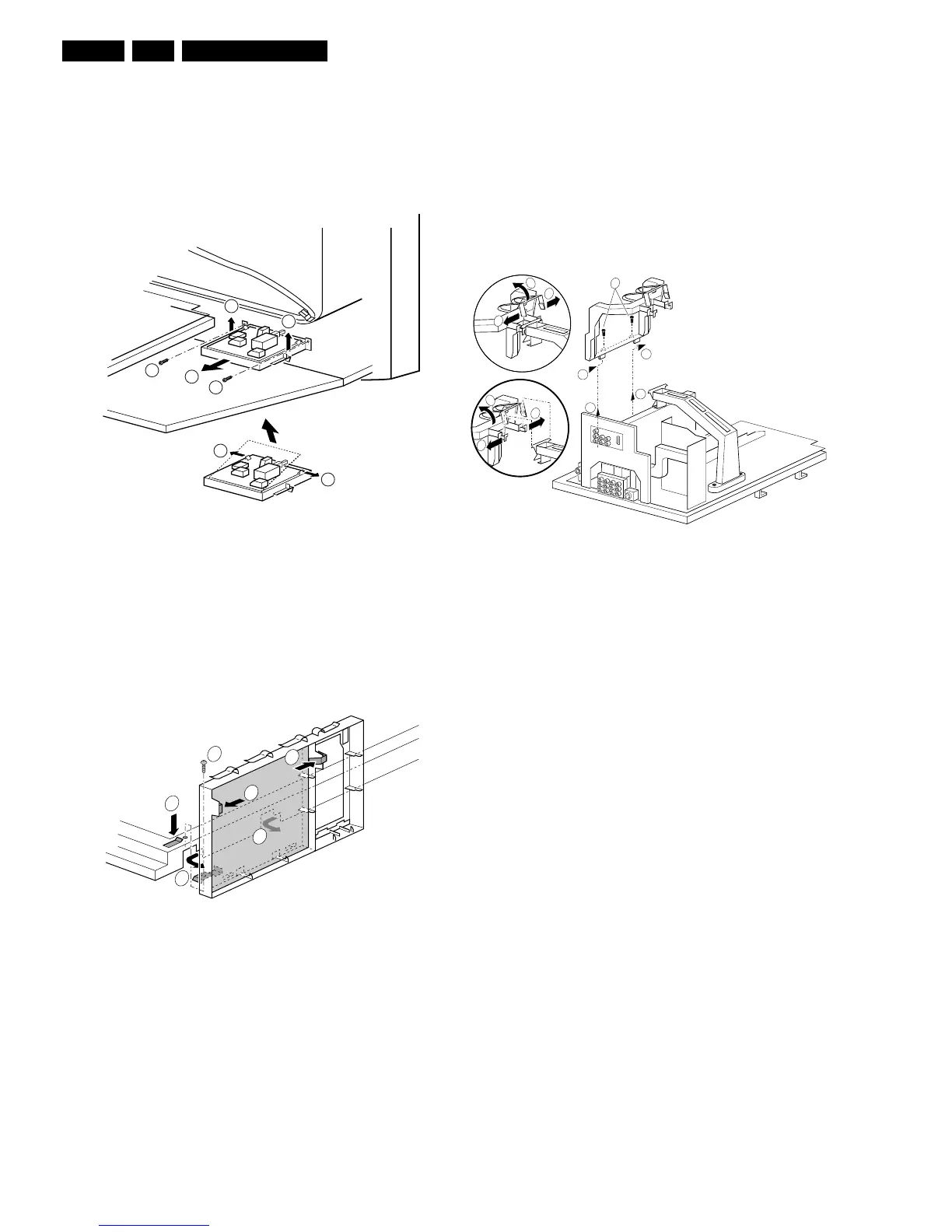
4.4.6 Small Signal Board (SSB)
In fact, there is no predefined service position for the SSB. Most
test points are located on the A-side (side that is facing the
tuner).
If you have to replace ICs, you must take the complete SSB
module out of the SIMM-connector.
To get access to the SSB test points, do the following:
1. Put the LSP in service position 1 (as described above).
2. Remove the fixation screws, which hold the SSB-bracket
(1).
3. Release the clamping jaw at the top of the SSB bracket (2)
and (3).
4. Push the two clamping lugs outwards, and pull the top of
the bracket at the same time upwards (4) and (5).
5. Now you can remove the complete bracket. Push it, at the
height of the LSP-bracket, towards the CRT (6) and lift it
out of the LSP-bracket (7).
6. Take the SSB out, disconnecting it from the LSP.
Figure 4-11 Small signal board
Notes:
• For better access to the SSB, it is possible to order an
"extension tool" with cables. You can use this service
extension tool to connect a Small Signal Board (SSB) of an
Axx or EMx chassis, via two "IDE" cables to the SIMM
connector in the set. In this way, you can service the SSB
more easily outside the TV set. You can order this tool
under 12nc: 9965 000 14526.
• If necessary for the measurement, you can put the LSP in
the "service position 2" (as described above).
4.4.7 Large Signal Panel (LSP)
1. Remove the HDMI assy (see paragraph "HDMI assy/panel
above).
2. Remove the SSB (see paragraph "Small Signal Board
(SSB)" above).
3. Disconnect the necessary cables.
4. Remove the fixation screw, which is located nearby the
SIMM-connector.
5. Release the fixation clamps on the left of the LSP-bracket
(the panel hinges at the right side).
6. Remove the panel from the bracket.
4.5 Set Re-assembly
To re-assemble the whole set, do all processes in reverse
order.
Note: be sure that, before the rear cover is mounted:
• The mains cord is mounted correctly in its guiding brackets.
• All wires/cables are returned in their original positions. This
is very important due to the large "hot" area of the set
3
3
1
2
2
1
3
E_13950_005.eps
270204
1
E_13950_014.eps
040304
4
1
3
4
3
2
E_13950_003.eps
030304
7
6
7
6
4
4
2
5
3
2
1