Mechanical Instructions
EN 9A02U AA 4.
4.3 Service Positions
This chassis has several predefined service positions, for
better accessibility. They are explained below in more detail.
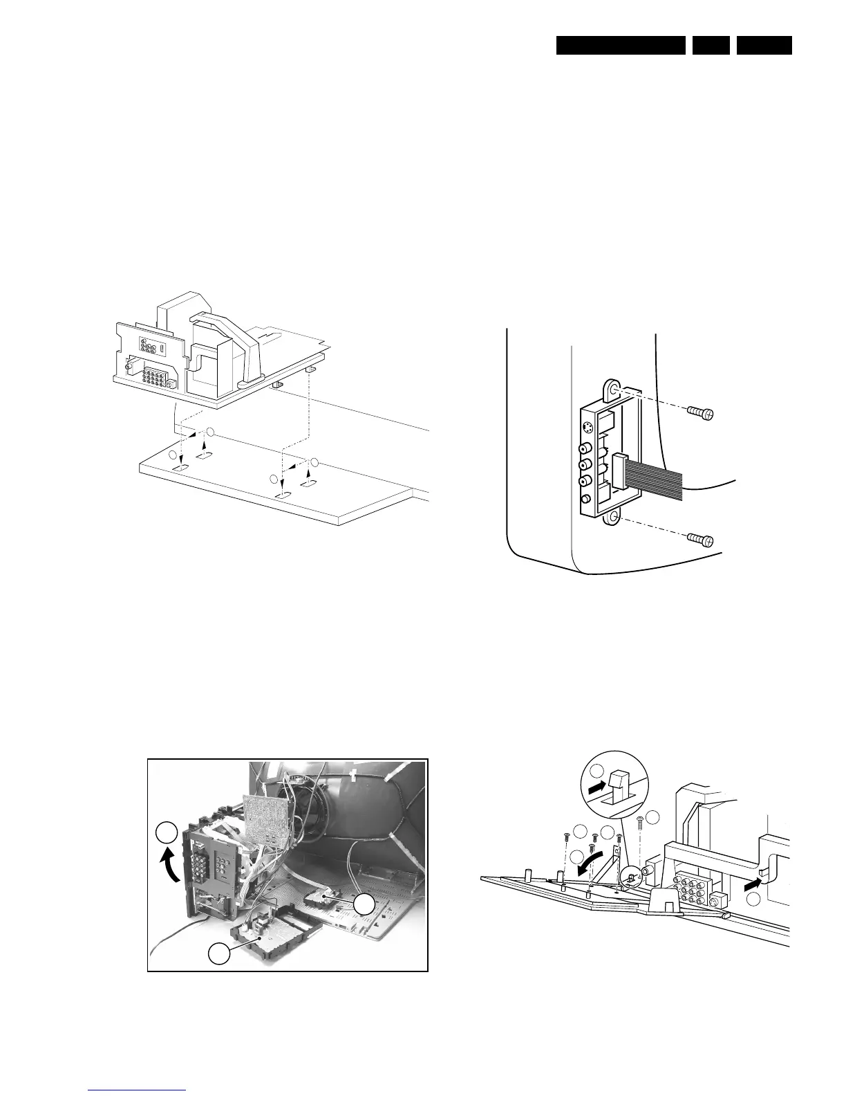
4.3.1 Large Signal Panel (LSP)
Service position 1 - Component Side of the LSP
For better accessibility of the LSP, do the following (see Figure
"Service position 1"):
1. Remove the LSP-bracket from the bottom tray by pulling it
backwards.
2. Hook the bracket in the first row of fixation holes of the
bottom tray. In other words, reposition the bracket from (1)
to (2).
Figure 4-5 Service position 1
Service position 2 - Solder Side of the LSP
To get access to the bottom side (solder side) of the LSP, do
the following (see figure above):
1. Remove the DC-Shift assy (1) (see paragraph "DC-Shift
Assy/Panel" below).
2. Release the Front interface assy from the bottom plate (2)
(see paragraph "Top Control Assy/Panel" below).
3. Disconnect the degaussing coil from the LSP. Therefore
remove the cable from the connector 1502 .
4. Release some wiring from their fixation clamps, in order to
get room for repositioning the LSP.
5. Flip the LSP 90 degrees clockwise (3), and place it
vertically on the bottom plate and a table.
Figure 4-6 Service position 2
4.4 Assies/Panels Removal
Sometimes, it can be necessary to swap a complete assy or
Printed Wiring Board (PWB). How that can be done is
explained below.
4.4.1 Top Control Assy/Panel
1. Remove the two fixation screws:
– PV2 styling: assy is mounted into the front cabinet;
– FL13 styling: assy is mounted into the rear cover.
2. Push the assy a little bit upwards, and then pull it
backwards to release it from the front hinge.
3. Lift the panel from its bracket, while releasing the four
fixation clamps.
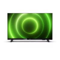
4.4.2 Side I/O Assy and Panel
Figure 4-7 Side-I/O assy/panel
1. Remove the two fixation screws, and remove the complete
Side I/O assembly.
2. Release the two fixation clamps, and lift the panel from the
bracket.
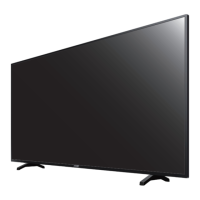
4.4.3 HDMI Assy/Panel Removal
Figure 4-8 HDMI assy/panel
E_13950_007.eps
100304
2
1
1
2
E_13950_009.eps
040304
3
2
1
E_14480_050.eps
170204
E_13950_004.eps
030304
2