Circuit Descriptions, Abbreviation List, and IC Data Sheets
EN 65LC8.1E LB 9.
9.8 IC Data Sheets
This section shows the internal block diagrams and pin layouts
of ICs that are drawn as "black boxes" in the electrical diagrams
(with the exception of "memory" and "logic" ICs).
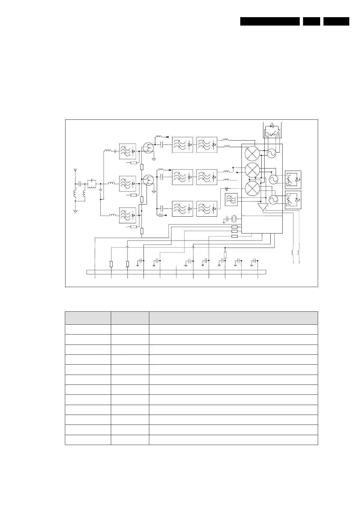
9.8.1 Diagram B02, Type UV1316E (IC1104), Tuner
Figure 9-15 Internal block diagram and pin configuration
Block Diagram
Pin Configuration
G_16510_060.eps
221106
SYMBOL PIN DESCRIPTION
AGC 1 Automatic Gain Control Voltage
TU 2 Tuning voltage monitor (output)
AS 3 I
2
C-Bus Address Select
SCL 4 I
2
C-Bus Serial Clock
SDA 5 I
2
C-Bus Serial Data
n.c. 6 Not Connected
V
s
7 Supply Voltage +5V
ADC 8
ADC Input
(5)
V
ST
9 Fixed tuning Supply Voltage +33V
I.F out 2 / d.n.c 10 Symmetrical I.F output 2 / Do not connect for asymmetrical
I.F out 1 11 Asymmetrical I.F Output / Symmetrical I.F output 1
GND M1,M2,M3,M4 Mounting Tags (Ground)
AGC TU AS SCL SDA n.c 5V ADC 33V IF2/nc IF1
HIGH
5V
MID
5V
LOW
5V
PLL
1
IF2
nc
IF1