Alignments
EN 55LC8.1E LB 8.
8. Alignments
Index of this chapter:
8.1 General Alignment Conditions
8.2 Hardware Alignments
8.3 Software Alignments
8.4 Option Settings
Note: Figures below can deviate slightly from the actual
situation, due to the different set executions.
General: The Service Alignment Mode (SAM) is described in
chapter 5. Menu navigation is done with the CURSOR UP,
DOWN, LEFT or RIGHT keys of the remote control transmitter.
8.1 General Alignment Conditions
Perform all electrical adjustments under the following
conditions:
• Power supply voltage (depends on region):
– AP-NTSC: 120 VAC or 230 VAC / 50 Hz (± 10%).
– AP-PAL-multi: 120 - 230 VAC / 50 Hz (± 10%).
– EU: 230 VAC / 50 Hz (± 10%).
– LATAM-NTSC: 120 - 230 VAC / 50 Hz (± 10%).
– US: 120 VAC / 60 Hz (± 10%).
• Connect the set to the mains via an isolation transformer
with low internal resistance.
• Allow the set to warm up for approximately 15 minutes.
• Measure voltages and waveforms in relation to correct
ground (e.g. measure audio signals in relation to
AUDIO_GND).
Caution: It is not allowed to use heatsinks as ground.
• Test probe: Ri > 10 Mohm, Ci < 20 pF.
• Use an isolated trimmer/screwdriver to perform
alignments.
8.2 Hardware Alignments
There are no hardware alignments foreseen for this chassis,
but below find an overview of the most important DC voltages
on the SSB. These can be used for checking proper functioning
of the DC/DC converters.
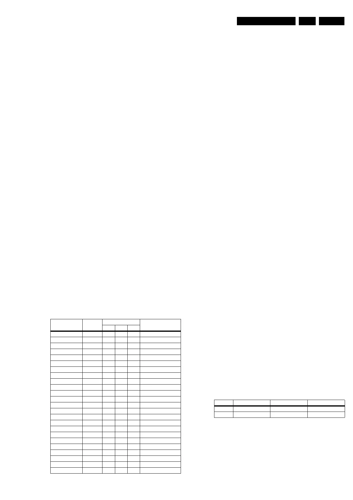
Table 8-1 DC voltages
8.3 Software Alignments
With the software alignments of the Service Alignment Mode
(SAM) the Tuner and RGB settings can be aligned.
To store the data: Use the RC button “Menu” to switch to the
main menu and next, switch to “Stand-by” mode.
8.3.1 Tuner Adjustment (RF AGC Take Over Point)
Purpose: To keep the tuner output signal constant as the input
signal amplitude varies.
The LC8.1E LB chassis comes with the UV1316E analogue
tuner. No alignment is necessary, as the AGC alignment is
done automatically (standard value: “15”). However in case of
problems use the following method (use multimeter and RF
generator):
• Apply a 70 dB (1mv) RF signal with a Philips standard
circuit pattern to antenna input.
• Adjust AGC (via SAM menu: TUNER -> AGC), until voltage
on pin 1 is 3.3 +0.5/-1.0 V.
• Store settings and exit SAM.
8.3.2 RGB Alignment
In RGB Alignment menu there are three items White Tone,
ADC Gain & Align ADC to perform the colour temperature
alignment for the RF and the input source calibration.
Before alignment, choose “TV MENU” -> “Picture” and set:
• “Brightness” to “50”.
• “Colour” to “50”.
• “Contrast” to “100”.
White Tone Alignment:
• Activate SAM.
• Select “RGB Align.” -> “White Tone” and choose a colour
temperature.
• Use a 100% white screen as input signal and set the
following values:
– All “White point” values initial to “255”.
In case you have a colour analyser:
• Measure with a calibrated (phosphor- independent) colour
analyser (e.g. Minolta CA-210) in the centre of the screen.
Consequently, the measurement needs to be done in a
dark environment.
• Adjust the correct x,y coordinates (while holding one of the
White point registers R, G or B on “256”) by means of
decreasing the value of one or two other white points to the
correct x,y coordinates (see table “White D alignment
values”). Tolerance: dx: ± 0.004, dy: ± 0.004.
• Repeat this step for the other colour Temperatures that
need to be aligned.
• When finished return to the SAM root menu and press
STANDBY on the RC to store the aligned values to the
NVM.
Table 8-2 White D alignment values
If you do not have a colour analyser, you can use the default
values. This is the next best solution. The default values are
average values coming from production (statistics).
• Set the RED, GREEN and BLUE default values per
temperature according to the values in the “Tint settings”
table.
• When finished return to the SAM root menu and press
STANDBY on the RC to store the aligned values to the
NVM.
Description Test Point Specifications (V) Diagram
Min. Typ. Max.
+VTUN FP14 30 33 36 B01_DC-DC
+12V_AUDIO FP06 11.40 12.00 12.60 B01_DC-DC
-12V_AUDIO FP09 -11.40 -12.00 -12.60 B01_DC-DC
+12V_DISP FP04 11.40 12.00 12.60 B01_DC-DC
+3V3_STBY FP01 3.20 3.30 3.40 B01_DC-DC
+5V_SW FP05 4.90 5.16 5.42 B01_DC-DC
+2V5_SW FP18 2.40 2.50 2.60 B01_DC-DC
+1V8_SW FP03 1.70 1.80 1.90 B01_DC-DC
+3V3_SW_TDA FP19 3.10 3.30 3.50 B01_DC-DC
+1V8_SW_ADC FP20 1.70 1.80 1.90 B01_DC-DC
+3V3_SW FP22 3.10 3.30 3.50 B01_DC-DC
+8V_SW FP21 7.60 8.00 8.40 B01_DC-DC
+5V_IF F133 4.75 5.00 5.25 B02_Tuner IF & SAWF
+5V_TUN F111 4.75 5.00 5.25 B02_Tuner IF & SAWF
+5V_SW_SMIC F402 4.75 5.00 5.25 B05A_SMIC L
VDDA FA01 11.40 12.00 12.60 B05B_Audio - CLASS D
VDD FA03 11.40 12.00 12.60 B05B_Audio - CLASS D
VSSA FA02 -11.40 -12.00 -12.60 B05B_Audio - CLASS D
VSS FA14 -11.40 -12.00 -12.60 B05B_Audio - CLASS D
+5VHDMI_A FN08 4.75 5.00 5.25 B06B_HDMI
+5VHDMI_B FN13 4.75 5.00 5.25 B06B_HDMI
+1V8_ANA-MUX FN03 1.70 1.80 1.90 B06B_HDMI
+1V8_DIG-MUX FN02 1.70 1.80 1.90 B06B_HDMI
+3V3_ANA-MUX FN74 3.10 3.30 3.50 B06B_HDMI
Value Cool (11000 K) Normal (9000 K) Warm (6500 K)
x 0.278 0.289 0.314
y 0.278 0.291 0.319