Service Modes, Error Codes, and Fault Finding
EN 11LGE PDP 5.
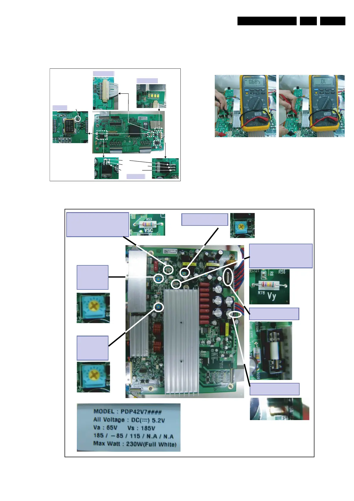
Control Board (see figure “Control b/d trouble shooting”)
1. Check LED status (normal status lightening or not)
2. If not, check OSC X1 output.
3. Check CTRL input voltage (connector P10).
4. Check each FET (3.3V, 5V, and 1.8V).
Figure 5-9 Control b/d trouble shooting
Y-SUS Board (see figure “Y-SUS b/d trouble shooting“)
1. Check fuse: FS1 (5V), FS2 (Vs).
2. Check voltages (Vsetup, -Vy, and Vsc).
3. Check diode between GND and Y-SUS output.
4. Check whether output voltages agree with voltages on the
label.
Figure 5-10 Y-SUS board output diode check
Figure 5-11 Y-SUS b/d trouble shooting
F_15590_072.eps
060705
3.3 V
5 V
1..8 V
LED
Input voltage
OSC(X1)
Probe
touching
point
Check FET
Check oscillating state.
Be careful with physical shock.
DMM – (GND)
F_15590_074.eps
290605
Normal diode value= 0.6 (forward)
Normal diode value = OL (reverse)
F_15590_073.eps
060705
Vsc check point
(measure over R53)
Vy adjust
Vy check point
(measure over R78)
Vset_dn
adjust
Vs fuse
Vset_up
adjust
5V fuse
 Loading...